
Waste to liquid hydrocarbon refinery system

Inactive Publication Date: 2011-06-30
ALVES RAMALHO GOMES MARIO LUIS
View PDF6 Cites 71 Cited by
  • Summary
  • Abstract
  • Description
  • Claims
  • Application Information

AI Technical Summary

Benefits of technology

[0012]This means that with our WTLH solution, particularly via its plasma gasification stage, we will ensure the required purity for the resulting SYNGAS, thus removing all the concerns about catalyst poisoning or environment contamination.
[0015]ii) A method and solution that will help to solve the modern society problem of fossil fuel dependence, by reducing the need for fuel imports, reducing the dependence on limited stock fuel resources and increasing the stock safety reliability.
[0017]iv) A method and solution that will help solving the summer fire problems in dry countries by creating a useful market for any type of biomass and forest residues conversion into synthetic hydrocarbons.
[0024]xi) A method and solution for producing renewable synthetic hydrocarbon fuels, wherein synthetic hydrocarbons, electricity, heat and vitrified and metal sub-products are all market valuable outputs and where there are no environment emissions or residues coming out of the whole system, making it an environmentally sound and sustainable tetra-generation solution.

Problems solved by technology

Such conventional refinery systems do not allow mixed feedstock types and have a typical 6:1 yield of synthetic fuel (i.e. 1 ton of Natural Gas or Coal will allow the production of about 0.17 ton of FT products).
However, since GTL has Natural Gas as its feedstock and CTL uses coal, despite its recognised advantages relatively to fossil crude oil, the point is that either via GTL or CTL we will not acquire freedom and independence from fossil fuels.
This means also that current GTL and CTL units will not prevent Global Climate Change.
Furthermore, conventional GTL and CTL units have a carbon conversion ratio not better than 65%, i.e. 35% of the whole carbon contained in the original feedstock (natural gas (NG) or Coal) will not be transformed into FT products (it will be lost as carbon dioxide into the atmosphere).
Choren gasification system is not able to deal with Municipal or Hazardous Waste feedstocks (MSW or HW) or other diversified carbon containing feedstocks.

Method used


Image

  • Waste to liquid hydrocarbon refinery system
  • Waste to liquid hydrocarbon refinery system
  • Waste to liquid hydrocarbon refinery system

Examples


case 2

er with the Original Feedstock SYNGAS, Steam is Injected as an Input Reactant to the FT Reactor:

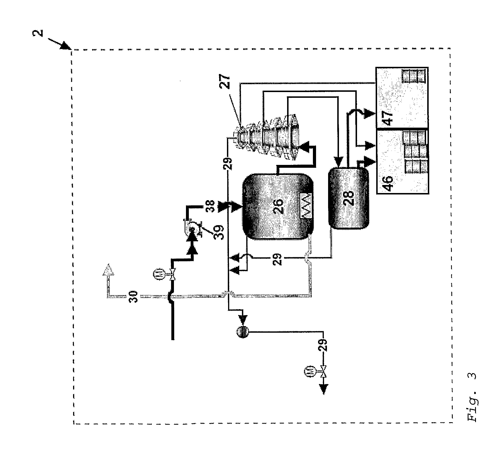
[0073]In order to reduce the C lost in the synthesis of hydrocarbon at the FT reactor (26), Case 1- can be modified by adding external steam coming, for example, from the Steam Turbine (20) at subsystem 3. With an increase in the H2O content at the FT reactor, Le Chatelier principle will create an equilibrium bias at the WGS reaction towards the formation of more H2, increasing thus the H2 to CO ratio and minimising further losses of SYNGAS CO. Again, at WGS equilibrium the rate of consumption of CO+H2 is independent of the extent of the WGS reaction, since CO and H2 are on opposite sides of the WGS equation, but since more H2 than what comes in via the original SYNGAS is now available, the amount of Alkanes and Alkenes that can be generated is now also greater than in Case 1-. In such case, the expected hydrocarbon yield, represented by the C12H26 yield, is governed by the equation:

ssCO+...


PUM


Abstract

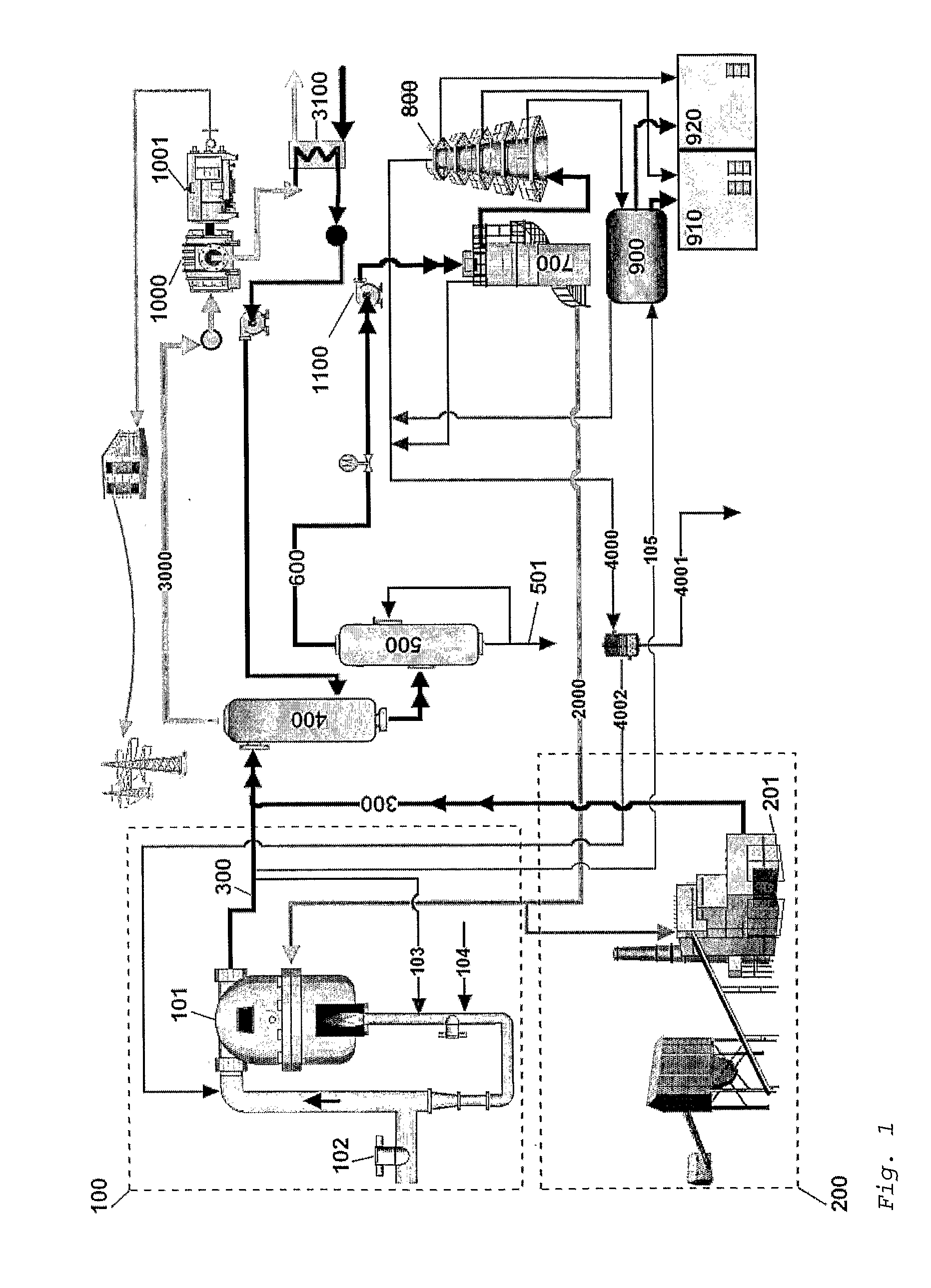
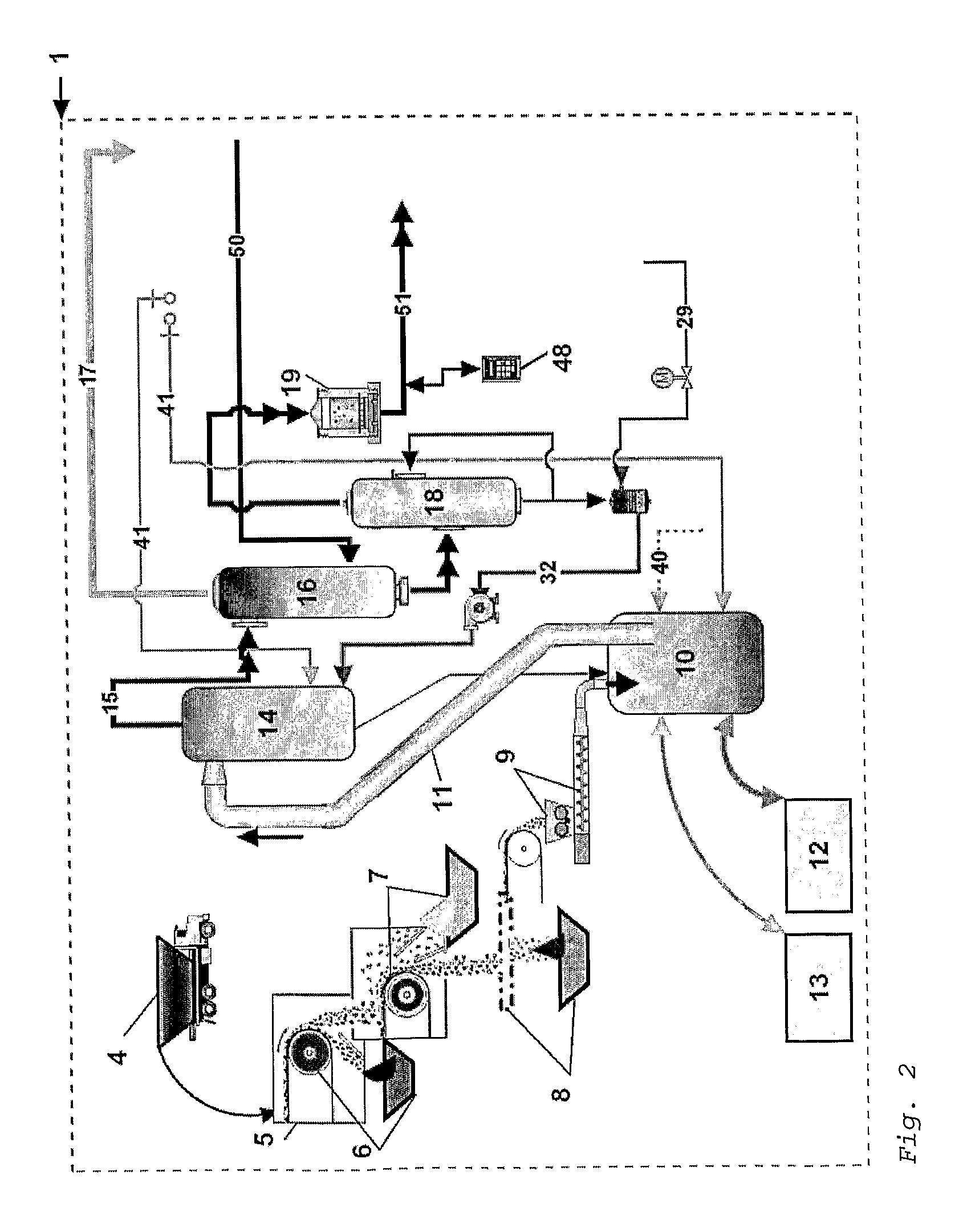
A Waste to Liquid Hydrocarbon Refinery System that transforms any municipal solid wastes and hazardous industrial wastes, Biomass or any carbon containing feedstock into synthetic hydrocarbon, particularly, but not exclusively, diesel and gasoline and / or electricity and co-generated heat, comprising three major subsystems: i) the Pyro-Electric Thermal Converter (PETC) (10) and Plasma Arc (PA) waste and biomass gasification subsystem (1); ii) the hydrocarbon synthesis subsystem (2); and iii) the electricity generation and heat co-generation subsystem (3).

Description

1—PRIOR ART[0001]The starting point configuration is a Conventional Gas to Liquid (GTL) or a Coal to Liquid (CTL) Refinery system where, respectively, Natural Gas (methane) or coal is submitted to a gasification process to produce SYNGAS (Synthetic GAS) (hydrogen and carbon monoxide). SYNGAS is then used to synthesise liquid hydrocarbon species using a Fischer-Tropsch (FT) reactor, eventually combined with a distillation column and an hydrocracking reactor. Such conventional refinery systems do not allow mixed feedstock types and have a typical 6:1 yield of synthetic fuel (i.e. 1 ton of Natural Gas or Coal will allow the production of about 0.17 ton of FT products). Companies like Syntroleum, MossGas and Shell are engaged with GTL technologies. Companies like Sasol and Rentech are particularly engaged with CTL process, but deal also with GTL. Furthermore, ExxonMobil, Marathon and ConocoPhillips are announcing future investments in new GTL facilities.[0002]Oil and fuel prices have cr...

Claims


Application Information

Patent Timeline
IPC IPC(8): B01J8/00
CPCC01B3/042C10G2400/04C10B49/14C10G2/332C10J3/00C10J3/57C10J3/66C10J3/721C10J2300/0903C10J2300/0906C10J2300/0916C10J2300/0946C10J2300/1238C10J2300/1659C10J2300/1671C10J2300/1675C10J2300/1687C10J2300/1884C10J2300/1892C10K1/002C10K1/08C10K1/32C10K3/04F01K13/00F22B1/18Y02E20/12Y02E50/32Y02E60/364C10G2300/1003C10G2300/1011C10G2300/1022C10G2300/205C10G2300/4081C10G2300/42C10G2400/02C01B3/12Y02E50/30Y02E60/36Y02P20/129Y02P20/145Y02P30/20
Inventor ALVES RAMALHO GOMES, MARIO LUIS
Owner ALVES RAMALHO GOMES MARIO LUIS
Learn More