
Optical film and method for manufacturing the same

a technology of optical film and polarizing plate, which is applied in the field of optical film, can solve the problems of liquid crystal display having sufficient contrast ratio, affecting the appearance so as to improve the contrast ratio of liquid crystal display, suppress the generation of light unevenness, and control the effect of light unevenness

Active Publication Date: 2011-06-30
FUJIFILM CORP
View PDF3 Cites 23 Cited by
  • Summary
  • Abstract
  • Description
  • Claims
  • Application Information

AI Technical Summary

Benefits of technology

[0010]In view of such present situation, objects of the invention are to provide an optical film capable of controlling light unevenness and improving the contrast ratio of a liquid crystal display, and a manufacturing method of the same.
[0012]A further object is to provide a polarizing plate using the optical film. A still further object of the invention is to provide a liquid crystal display having a high contrast ratio and improved in light unevenness.
[0034]According to an exemplary embodiment of the invention, it is possible to provide an optical film capable of controlling generation of light unevenness and improving the contrast ratio of a liquid crystal display. By the use of an optical film of the invention, the generation of light unevenness of the liquid crystal display can be suppressed and contrast ratio can be improved.

Problems solved by technology

For example, with the progress of thinning of liquid crystal displays, there arises a problem such that light unevenness, which seems like a circle or an ellipsoid occurs on the screen, and the improvement thereof is required.
As a cause of generation of such light unevenness, it is indicated that the contact of a backlight member and a polarizing plate on the backlight side of a liquid crystal panel member is liable to occur due to thinning of a liquid crystal display.
It is thought that when a liquid crystal display is used for a long period of term in the state of a backlight member and a polarizing plate on the backlight side being in contact with each other or a liquid crystal display is used under high temperature high humidity environment, water content is liable to gather at the contact area and the water content penetrates through to the polarizer, as a result the performance of the polarizing plate deteriorates to thereby cause light unevenness.
However, it has been found that liquid crystal displays having sufficient contrast ratio cannot be obtained with the optical films disclosed in Patent WO 09 / 047,924 and WO 09 / 081,607.
However, it has been found that a film itself is softened by the addition of a large amount of an acrylic resin such as PMMA and a problem arises such that the film ruptures by stretching in high magnification.

Method used


Image

  • Optical film and method for manufacturing the same
  • Optical film and method for manufacturing the same

Examples


examples

[0202]The invention will be described in detail below with reference to examples, but the invention is not restricted to these examples.

(Manufacture of Optical Films 101 to 132 and 141)

(Preparation of Dope)

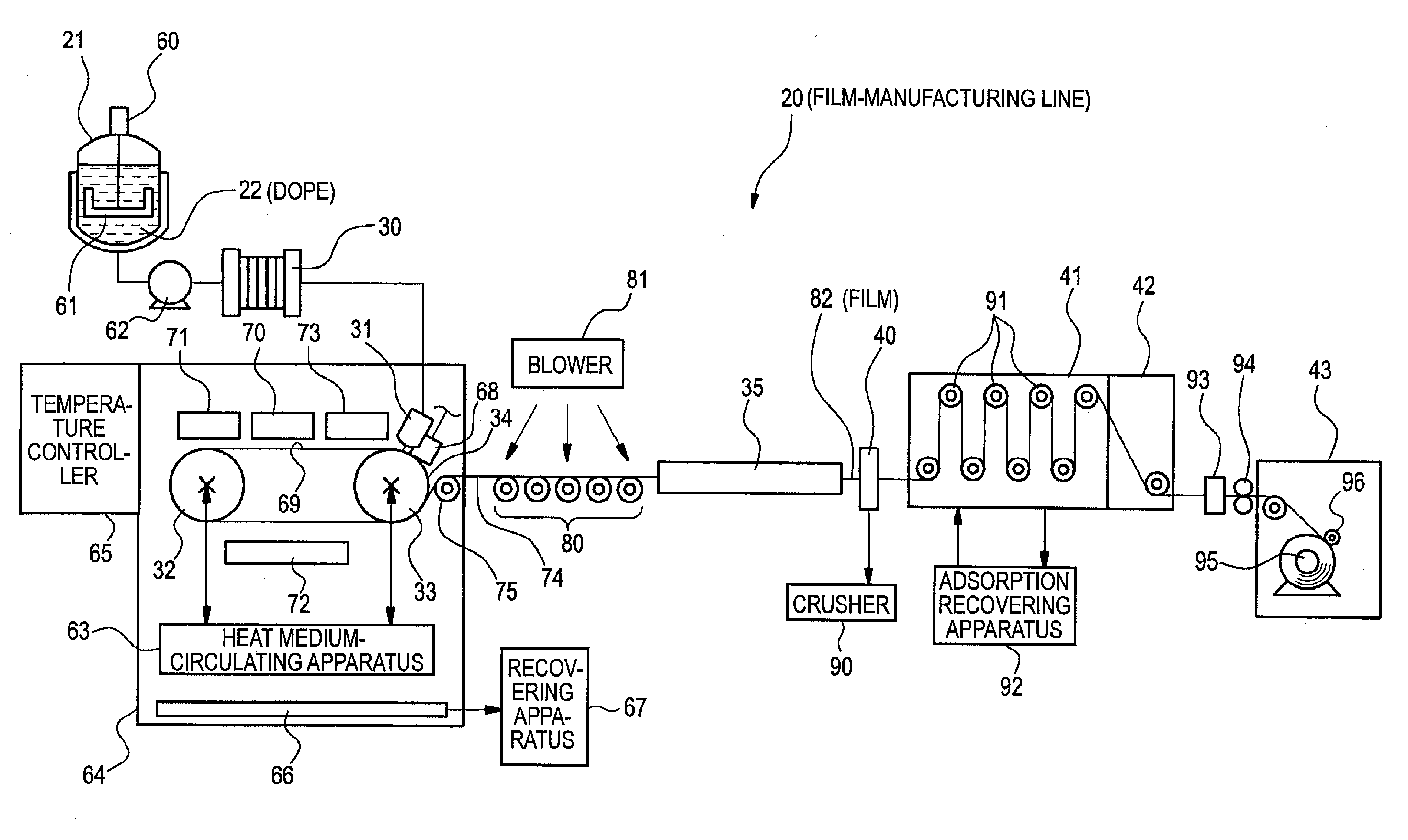
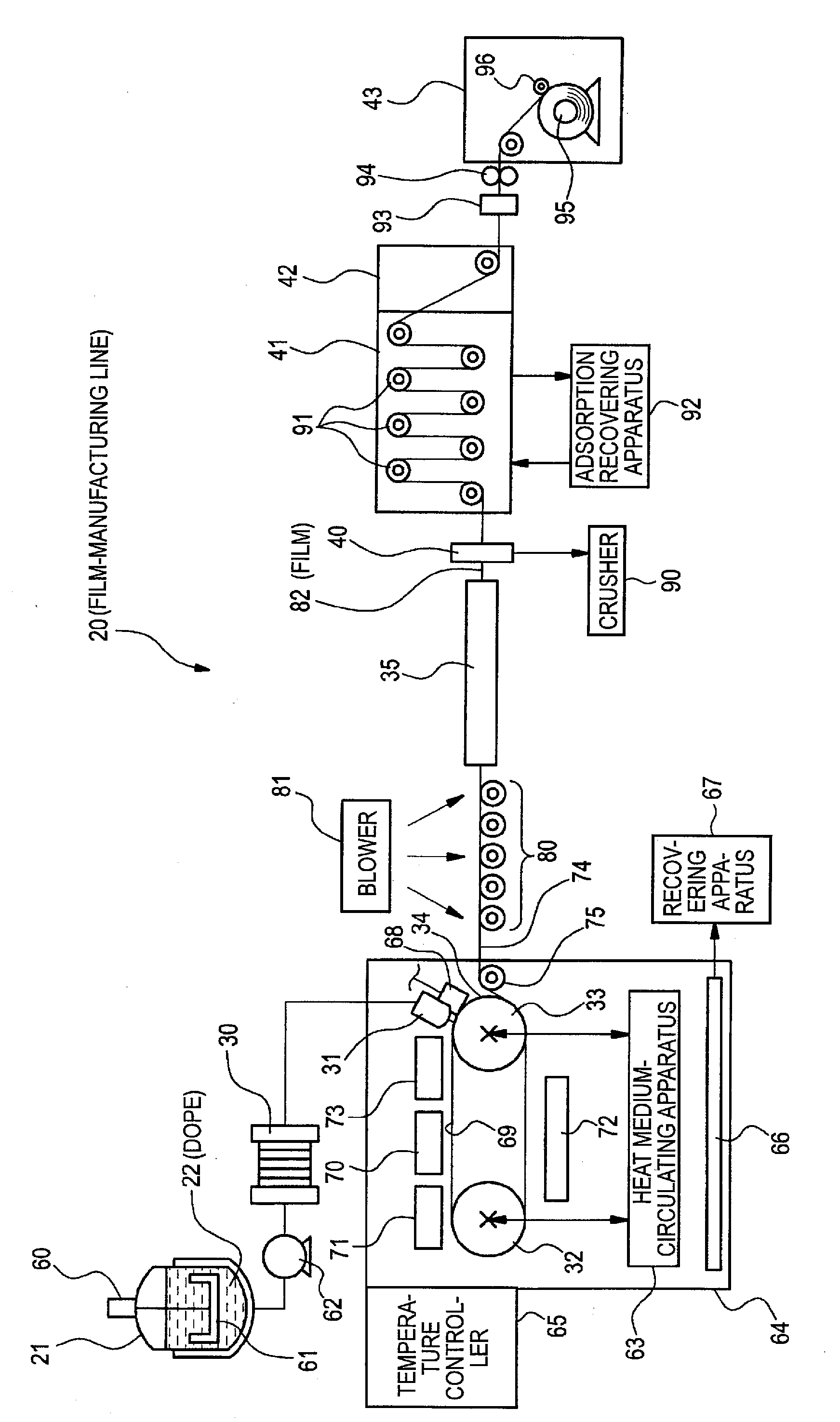
[0203]The following-shown composition is put in a mixing tank, stirred while heating to be dissolved, thus a dope is prepared.

(Composition of Dope)

[0204]

Acrylic resin A (DIANAL BR85, manufactured by67 parts by massMitsubishi Rayon Co., Ltd.)Cellulose ester A33 parts by mass(cellulose acetate propionate, total degree ofsubstitution of acyl group: 2.5, degree ofsubstitution of acetyl group: 0.4, degreeof propionyl substitution: 2.1, Mw = 200,000)Dichloromethane264 parts by massEthanol36 parts by mass

[0205]The cellulose ester used here is as follows.

[0206]To cellulose is added sulfuric acid as a catalyst (7.8 parts by mass to 100 parts by mass of cellulose), carboxylic acid is then added as the starting material of acyl substituent, and acylation reaction is carried out at 40° C. At...


PUM

PropertyMeasurementUnit
wavelengthaaaaaaaaaa
mass ratioaaaaaaaaaa
modulus of elasticityaaaaaaaaaa

Abstract

An optical film is provided and includes a cellulose ester and an acrylic resin. The mass ratio of the cellulose ester to the acrylic resin is 70 / 30 to 5 / 95, the total haze value of the optical film is 0.80 or less, the internal haze value of the optical film is 0.01 to 0.28, and the modulus of elasticity in the transverse direction of the optical film is 2,700 to 7,000 MPa.

Description

[0001]This application is based on and claims priority under 35 U.S.C. §119 from Japanese Patent Application No. 2009-298576, filed Dec. 28, 2009, the entire disclosure of which is herein incorporated by reference.BACKGROUND OF THE INVENTION[0002]1. Field of the Invention[0003]The present invention relates to an optical film and a method for manufacturing the same.[0004]2. Background Art[0005]In recent years, liquid crystal displays are widely used in uses such as liquid crystal panels and the like, e.g., liquid crystal televisions, personal computers, portable telephones and digital cameras. In general, a liquid crystal display has a liquid crystal member having provided polarizing plates on both sides of a liquid crystal cell, and display is performed by controlling the light from the backlight member at the liquid crystal member. Here, the polarizing plate comprises a polarizer and the protective films on both sides of the polarizer. Ordinary polarizer can be obtained by dyeing a...

Claims


Application Information

Patent Timeline
Patent Type & Authority Applications(United States)
IPC IPC(8): G02F1/1335G02B5/30B29C55/12B29C39/14C08L1/10
CPCB29C41/28B29C55/08G02B5/3025C08L2203/16C08L33/12C08L1/10B29K2033/08B29K2001/00B29K2001/12C08L33/08
Inventor KAWANISHI, HIROYUKIFURUKAWA, HIROMICHI
Owner FUJIFILM CORP
Learn More