
Microwave supplying apparatus and microwave plasma system

a plasma system and microwave technology, applied in the direction of accelerators, electric discharge tubes, magnets, etc., can solve the problems of difficult to form a large-area and uniform electromagnetic wave construction, the plasma produced by the microwave with the microwave field appearance b>100/b> has a uniform problem, and the way of producing large-area and uniform plasma is difficul

Active Publication Date: 2011-06-30
NAT CHUNG SHAN INST SCI & TECH
View PDF2 Cites 21 Cited by
  • Summary
  • Abstract
  • Description
  • Claims
  • Application Information

AI Technical Summary

Benefits of technology

Another scope of the invention is to provide a power divider for the microwave supplying apparatus. The microwave supplying apparatus can provide a large-area and uniform microwave field through the power divider.

Problems solved by technology

The way of producing large-area and uniform plasma is a major issue in the relative field.
However, because of the short wavelength of microwave, it is difficult to form a large-area and uniform electromagnetic wave construction.
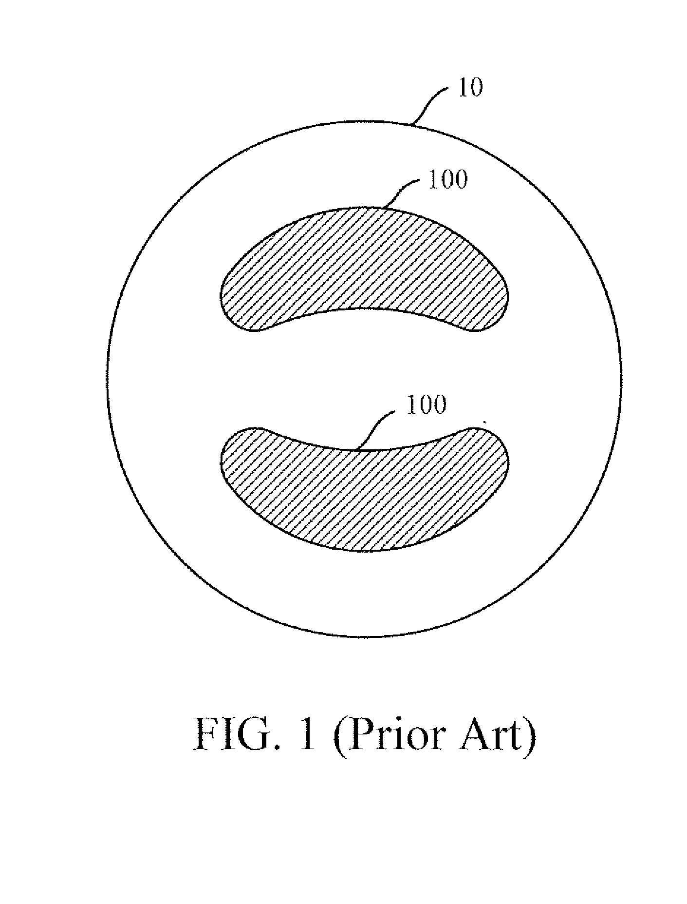
Though the plasma diffusion effect exists, the plasma produced by the microwave with the microwave field appearance 100 has a uniform problem.
The area of the chamber corresponding to the single micro generator is limited.
As mentioned above, the microwave field appearance focusing at two points may result in non-uniform ionization of plasma.
Besides, the conventional microwave dividing device only provides one-to-two effect in one level, so many levels of microwave dividing devices are needed to satisfy the requirement of the large area of the plasma processes in practice.

Method used


Image

  • Microwave supplying apparatus and microwave plasma system
  • Microwave supplying apparatus and microwave plasma system
  • Microwave supplying apparatus and microwave plasma system

Examples


Embodiment Construction

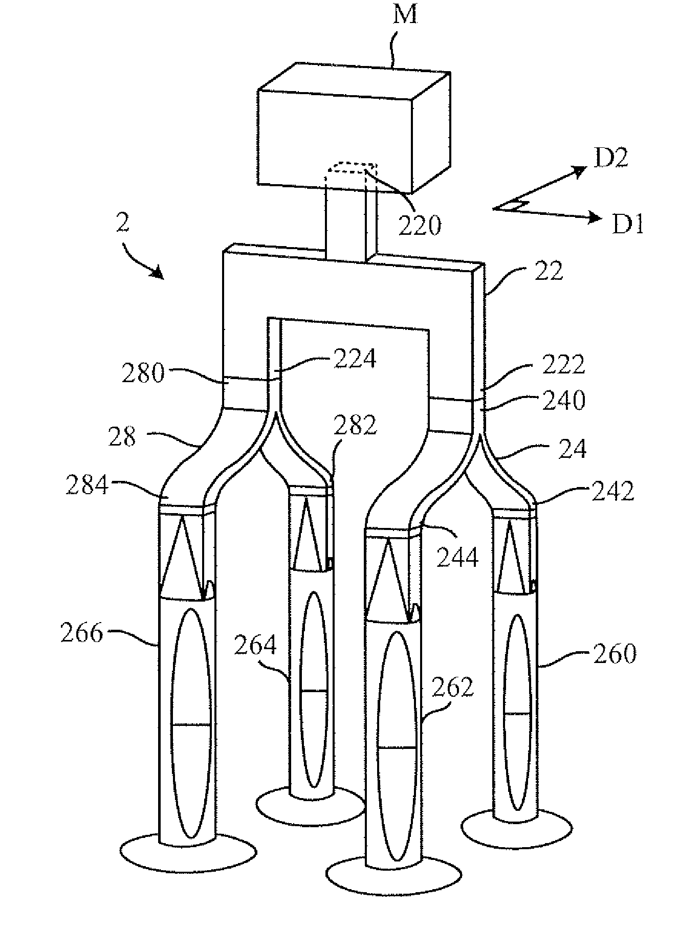
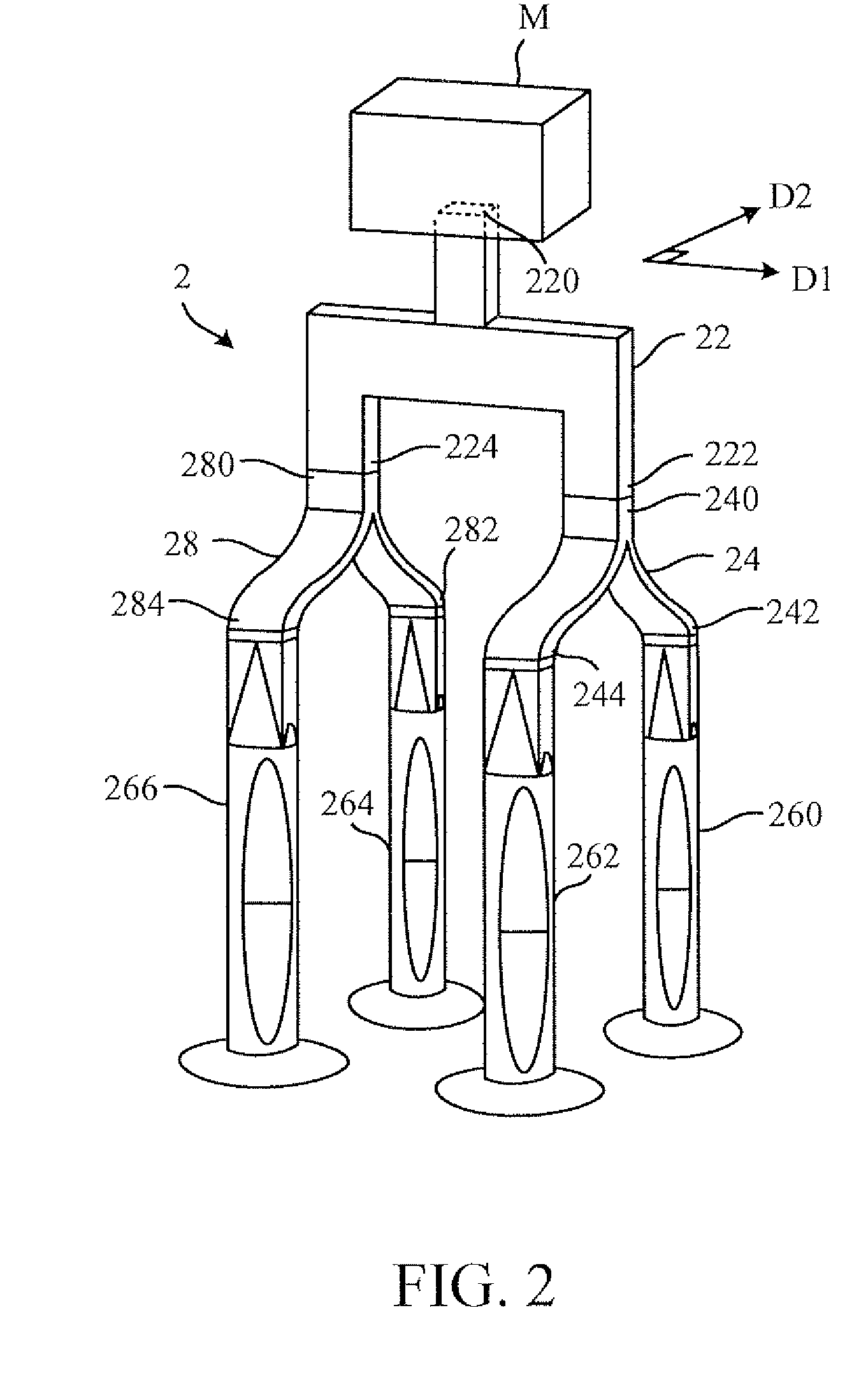
Please refer to FIG. 2. FIG. 2 is a schematic diagram illustrating the microwave supplying apparatus 2 according to an embodiment of the invention. As shown in FIG. 2, the microwave supplying apparatus 2 includes a first power divider 22, a second power divider 24, a first waveguide 260, and a second waveguide 262.

In this embodiment, the first power divider 22 has a first input terminal 220 capable of being connected to the microwave generator M, therefore the microwave generated by the microwave generator M could be transmitted to the first power divider 22. Besides, the first power divider 22 has a first output terminal 222 and a second output terminal 224 arranged along a first direction D1. The second power divider 24 has a second input terminal 240 capable of being connected to the first output terminal 222 of the first power divider 22, and the second power divider 24 further has a third output terminal 242 and a fourth output terminal 244 arranged along a second direction D2....


PUM


Abstract

The invention discloses a microwave supplying apparatus including a microwave generator, a first power divider, a second power divider, a first waveguide, and a second wave guide. The first waveguide is connected to the microwave generator and has a first output terminal and a second output terminal to divide a microwave generated by the microwave generator along a first direction. The second power divider is connected to the first output terminal and has a third output terminal and a fourth output terminal to divide the microwave along a second direction. The first waveguide and the second waveguide are connected to the third output terminal and the fourth terminal respectively and receive the microwave through the first power divider and the second power divider to respectively output the microwave fields with approximate intensity distributions.

Description

BACKGROUND OF THE INVENTION1. Field of the InventionThe invention relates to a microwave supplying apparatus and microwave plasma system, and particularly, the invention relates to a microwave supplying apparatus capable of supplying a large-area and uniform microwave field and relates to a microwave plasma system using the same.2. Description of the Prior ArtThe microwave plasma is an important tool for the thin film deposition, precision finishing, and surface modification. Because of the high density of ions and high degree of dissociation, the microwave plasma has great activity, reproducibility, and low reaction temperature, and it could be used for PECVD and plasma etching processes in low temperature. Therefore, the microwave plasma is meaningful for the development of large scale integrated circuit, microelectronic device, photoelectric and communication IC, polymer materials, and thin film sensor processes.Besides, in the electron cyclotron resonance (ECR) microwave plasma,...

Claims


Application Information

Patent Timeline
IPC IPC(8): H01P5/12
CPCH01P5/19H01P5/024
Inventor HUANG, CHUNG-CHUNCHANG, TSUN-HSULIN, BO-HUNGHU, CHI-WEN
Owner NAT CHUNG SHAN INST SCI & TECH
Learn More