Calcination method and system

a calcination method and system technology, applied in the field of calcination methods and systems, can solve the problems of undesired anhydrite (aiii) in gypsum, the energy required for such flash calcination is considerable, etc., and achieve the effects of reducing temperature, increasing product quality, and saving energy

Inactive Publication Date: 2011-06-23
CLAUDIUS PETERS PROJECTS
View PDF12 Cites 10 Cited by
  • Summary
  • Abstract
  • Description
  • Claims
  • Application Information

AI Technical Summary

Benefits of technology

[0015]In order to counter these disadvantages that accompany flash calcination, the invention provides an energy-neutral post-calcination in the downstream reaction vessel using the increased temperature of the gypsum, to be precise for a considerably longer period of time. A crucial part is played here by supplying the wet gas, which acts as a reaction gas for the post-calcination (the waste air from the upstream calcining mill is particularly suitable, since it has a water content of over 35% and, at over 150° C., is quite hot). Thanks to the water vapor thereby supplied, both the undesired anhydrite can be rehydrated and any double hydrate that is present can be further converted into hemihydrate.
[0016]The invention has recognized that supplying the wet gas is of decisive significance, since the water required for rehydrating the anhydrite is thereby supplied, and together with the thermally passive design there is also sufficient thermal energy available, without heating being required. The undesired fractions in the starting product of the calcining mill can in this way be reduced in an elegant manner and without requiring additional energy. The improvement in product quality is consequently achieved without increased operating costs. Although it is necessary for a sufficiently long dwell time to be maintained, this is not a disadvantage, since no costly energy supply is required.
[0018]Thanks to the invention, the calcination can be completed without requiring additional energy. The product quality is increased as a result, and consequently no longer restricted by the calcination quality of the calcining mill. The invention isolates the calcination quality of the calcining mill from that of the end product. Consequently, less calcination than in the prior art is adequate in the calcining mill. This means that the temperature there can be lowered, which saves energy; at the same time, the fraction of undesired anhydrite is thereby reduced.
[0019]By the post-calcination with a long dwell time in the reaction vessel, the invention also achieves a more uniform product. This not only increases the quality of the calcined gypsum, but also compensates for inflow fluctuations when the raw product is supplied. Fluctuations therefore no longer have adverse effects here on the product quality.
[0020]Apart from post-calcination, the reaction vessel also provides mixing-through of the gypsum. For this purpose, the reaction vessel is equipped with at least one fluidizing device. This allows caking or the forming of dead zones in the reactor to be prevented and produces more intensive mixing-through. The wet gas is advantageously used as fluidizing gas. However, it is also possible for this purpose to mix ambient air with the waste system air, in particular originating from the calcining mill. It is assumed hereafter that the supplied gas causes fluidizing of the bulk material. However, it is also possible that the gypsum is merely flowed around by the gas, without the advantages produced by fluid-like mixing being exploited. The mixing-through and the prevention of caking or the forming of dead zones may be achieved in some other way.
[0024]A further possibility of improving the product quality of gypsum without requiring extra thermal energy is that of speeding up the aging process. In the aging process, the gypsum begins to rehydrate at its surface, i.e. AIII constituents are converted into hemihydrate constituents.

Problems solved by technology

The energy required for such flash calcination is considerable.
Furthermore, undesired anhydrite (AIII) is produced in the gypsum.

Method used


Image

  • Calcination method and system
  • Calcination method and system
  • Calcination method and system

Examples


Embodiment Construction

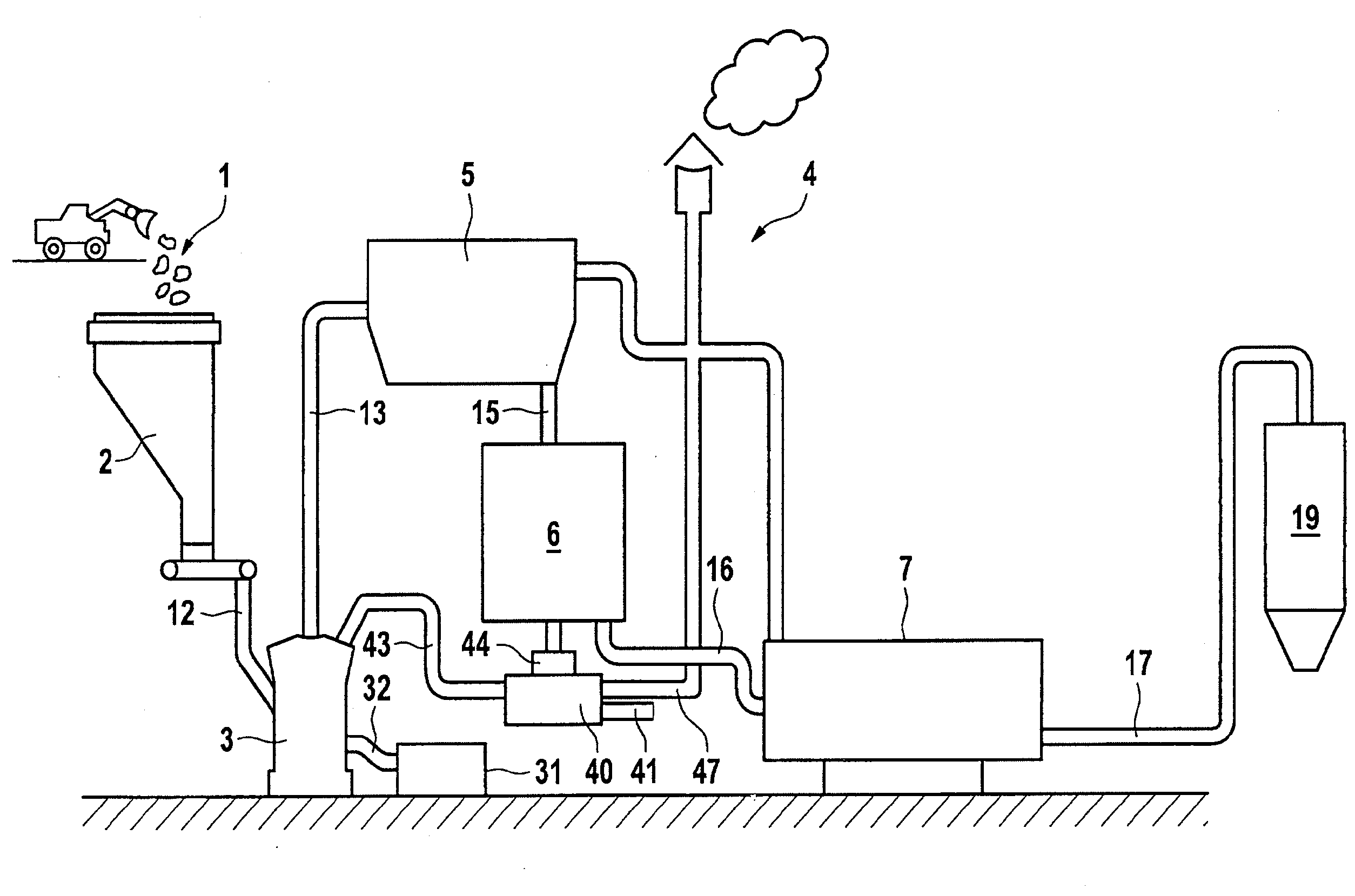
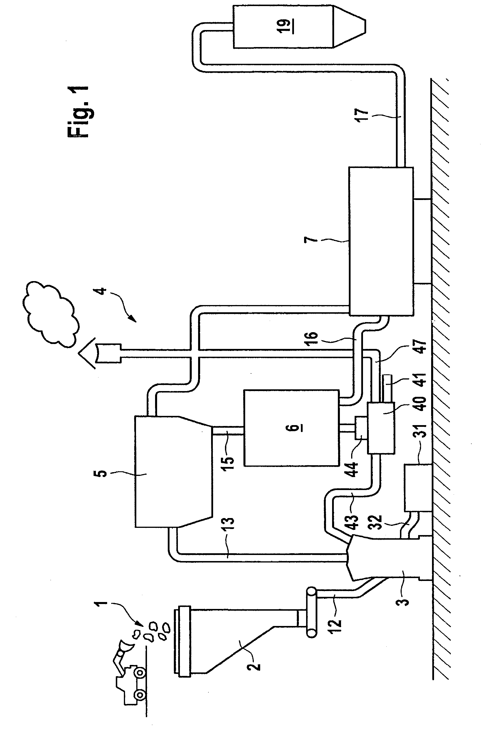
[0036]The device will be explained on the basis of an exemplary embodiment of an installation for calcining gypsum. Raw material for the gypsum to be calcined is introduced into the calcining installation at a charging point 1. The raw material may be, in particular, recycled gypsum products, such as gypsum building boards, and also so-called FGD gypsum from flue gas desulfurization installations (FGD). The application area of the invention is not only restricted to such gypsum but also extends to other types of synthetic gypsum, in particular phosphorus gypsum; however, natural gypsum may also be used. From the charging point 1, the gypsum raw material passes to an upper end of a storage silo 2. This is arranged in an elevated position and is located above a calcining mill 3.

[0037]The material to be calcined—in this case gypsum—is introduced via a line 12 into the calcining mill 3. In the calcining mill 3, the gypsum is comminuted and calcined. The calcination is performed as flash...


PUM

PropertyMeasurementUnit
dwell timeaaaaaaaaaa
temperatureaaaaaaaaaa

Abstract

A method for the calcination of powdery or fine-particled plaster includes steps in which the plaster is subjected to a flash-calcination in a calcinator and then post-calcinated in a reaction vessel. The post-calcination is carried out in the reaction vessel by adding humid gas, the reaction vessel not being heated. This post-calcination takes place over a long period of time, that is at least 10 times, preferably 50-100 times longer than, the amount of time taken for flash calcination. Complete calcination can take place without expending additional energy, and the remaining dihydrate produced during the flash calcination is also transformed into semi-hydrate and undesired anhydrite fractions are reduced. The method ensures consistency in the product quality and also increases product quality. The temperature in the upstream calcinator can be lowered to save energy. The method can also be used to accelerate the ageing of calcined plaster.

Description

REFERENCE TO RELATED APPLICATION[0001]This application is the national stage under 35 USC 371 of International Application No. PCT / EP2009 / 003321, filed May 11, 2009, which claims the priority of European Patent Application No. 08 008 734.9, filed May 9, 2008, the entire contents of which are incorporated herein by reference.FIELD OF THE INVENTION[0002]The invention relates to a method for calcining powdery or fine-grained gypsum, the gypsum first being calcined in a calcining mill before it is post-calcined in a reaction vessel. An installation for carrying out these methods and a retrofit reactor are likewise the subject of the invention.BACKGROUND OF THE INVENTION[0003]For calcining gypsum, the raw material is comminuted and, after drying (separation of free water), calcined in a reactor (separation of crystalline-bound water). For this purpose, the actual reactor may be preceded by a simple dryer with a burner (DE 37 38 301 A1) or complex fluidized bed dryers (DE 37 21.421 A1). G...

Claims


Application Information

Patent Timeline
Patent Type & Authority Applications(United States)
IPC IPC(8): C01F11/46B01J19/00
CPCB01J6/002B01J6/004B01J8/1836B01J2208/00274B01J2208/00557C04B11/0283B01J2208/0061B01J2208/00699C04B11/0286C04B11/007
Inventor GOECKE, VOLKERHILGRAF, PETER
Owner CLAUDIUS PETERS PROJECTS
Why Eureka
Try Eureka