Method and device for controlling the supply of a reducing agent to an scr system

a technology of reducing agent and scr, which is applied in the direction of instruments, separation processes, flue gas purification components, etc., can solve the problem of increasing the cost of the scr reactor

Active Publication Date: 2011-06-23
GENERAL ELECTRIC TECH GMBH
View PDF4 Cites 7 Cited by
  • Summary
  • Abstract
  • Description
  • Claims
  • Application Information

AI Technical Summary

Benefits of technology

[0007]An object of the present invention is to provide a method of controlling the supply of a reducing...

Problems solved by technology

This poses a problem, since a stoichiometric ratio between the NOx and the reducing agent is essential for achieving a good reduction of the NOx content of the flue gas and a low slip of the reduci...

Method used


Image

  • Method and device for controlling the supply of a reducing agent to an scr system
  • Method and device for controlling the supply of a reducing agent to an scr system
  • Method and device for controlling the supply of a reducing agent to an scr system

Examples


Embodiment Construction

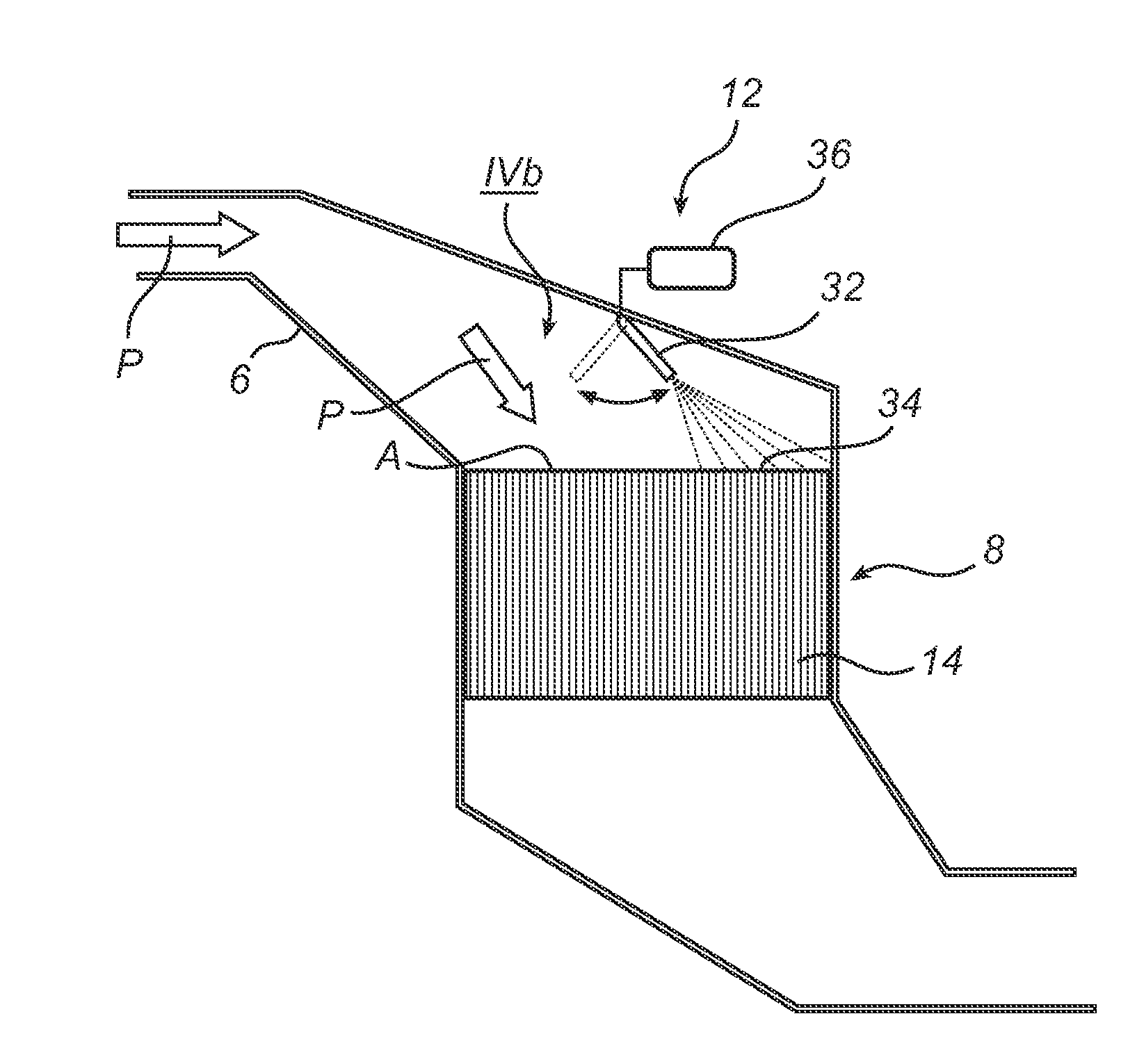
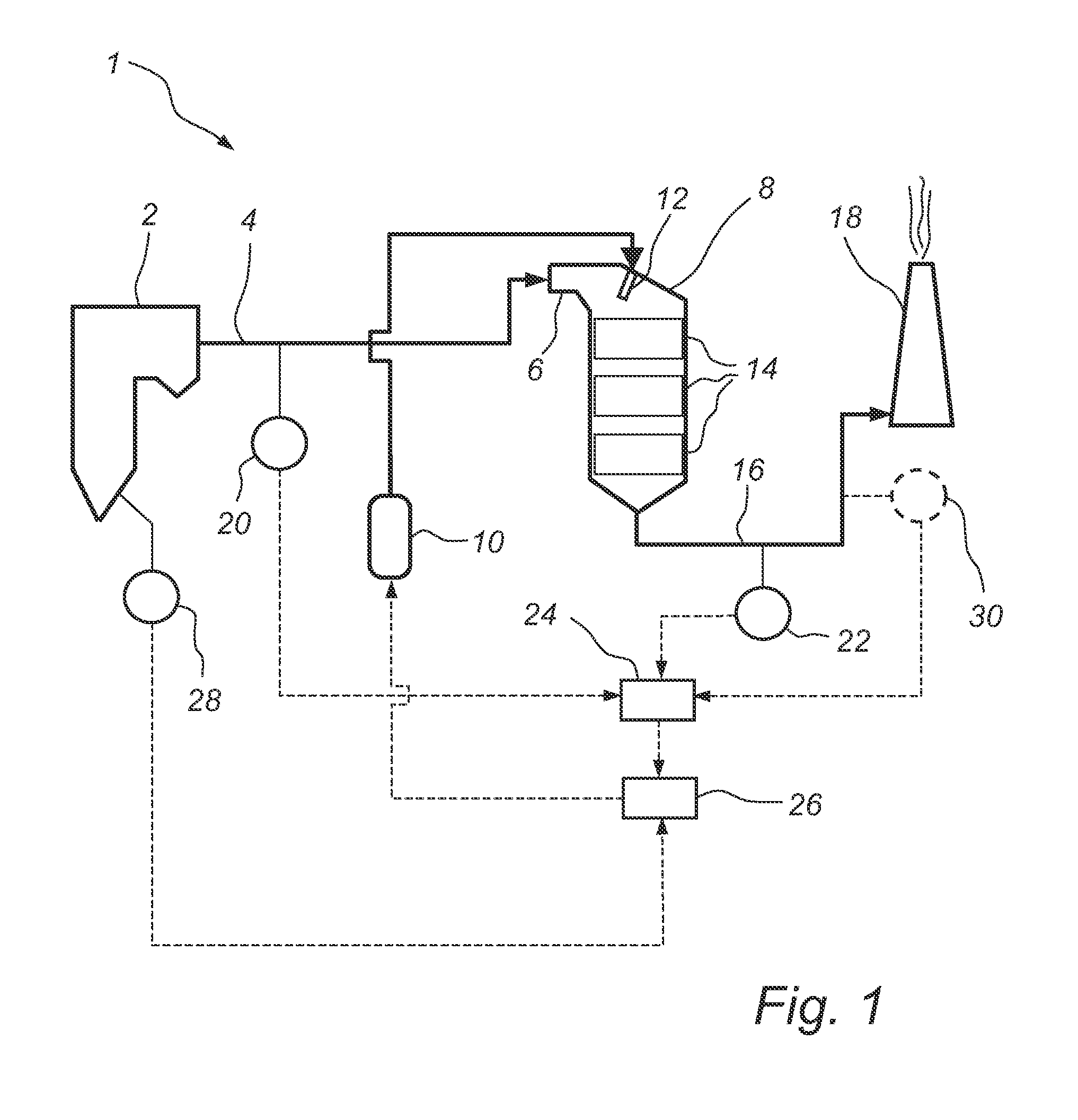
[0035]FIG. 1 is a schematic side view illustration of a power plant 1. The power plant 1 comprises a coal fired boiler 2. In the coal fired boiler 2 coal is combusted in the presence of air, thereby generating a flow of a process gas in the form of a flue gas that leaves the coal fired boiler 2 via a duct 4. The duct 4 forwards the flue gas to an inlet 6 of a selective catalytic reduction (SCR) reactor 8. An ammonia supply system 10 is operative for supplying ammonia to an ammonia-injection system 12. The ammonia injection system 12 supplies gaseous ammonia, NH3, to one or more consecutive layers 14 of SCR-catalyst located inside the SCR reactor 8. This SCR catalyst comprises a catalytically active component, such as vanadium pentoxide or wolfram trioxide, applied to a ceramic carrier material so as to comprise, e.g., a honeycomb structure or a plate structure. In the SCR reactor 8 the nitrogen oxides, NOx, in the flue gas react with the ammonia injected by means of the ammonia inje...


PUM

PropertyMeasurementUnit
Fractionaaaaaaaaaa
Fractionaaaaaaaaaa
Fractionaaaaaaaaaa

Abstract

A selective catalytic reduction reactor (8), which comprises at least one catalyst layer (14), is operative for removing NOx from a flow of process gas of a process plant, such as a combustion plant or an incineration plant. A device for controlling the feeding of a reducing agent, such as urea or ammonia, to said at least one catalyst layer (14), which has an attack area (A) facing the flow (P) of process gas, comprises at least one supply nozzle (32) which is operative for supplying reducing agent in at least one supply area (34) which corresponds to a part of the attack area (A), and a moving device (36) which is operative for moving said supply area (34) over the attack area (A).

Description

FIELD OF THE INVENTION[0001]The present invention relates to a method of controlling the feeding of a reducing agent, such as urea or ammonia, to a selective catalytic reduction reactor which comprises at least one catalyst layer and which is operative for removing NOx from a flow of process gas of a process plant, such as a combustion plant or an incineration plant.[0002]The present invention further relates to a device for controlling the feeding of a reducing agent, such as urea or ammonia, to a selective catalytic reduction reactor which is operative for removing NOx from a process gas of a process plant.BACKGROUND OF THE INVENTION[0003]In the combustion of a fuel, such as coal, oil, natural gas, peat, waste, etc., in a combustion plant, such as a power plant or a waste incineration plant, a process gas is generated. For separating nitrogen oxides, usually denoted NOx, from such a process gas, often referred to as a flue gas, a method is frequently used, in which a reducing agen...

Claims


Application Information

Patent Timeline
IPC IPC(8): B01D53/56B01J8/02G05D7/00
CPCB01D53/8631B01D53/8696B01D53/90B01D2251/2062F22B37/008F01N3/208F01N2610/02F01N2610/1453B01D2251/2067
Inventor LARSSON, MIKAEL
Owner GENERAL ELECTRIC TECH GMBH
Why Eureka
Try Eureka