Enhanced multi-user transmission

Active Publication Date: 2011-06-23
KONINKLIJKE PHILIPS ELECTRONICS NV
View PDF20 Cites 223 Cited by
  • Summary
  • Abstract
  • Description
  • Claims
  • Application Information

AI Technical Summary

Benefits of technology

[0022]It is an object of the present invention to provide a more flexible multi-user transmission scheme which requires less modifications of legacy devices and procedures.
[0025]The proposed transmitting apparatus may be adapted to create a transmission frame only from packets destined to at least one of those other transmission ends which replied to the request for transmission. The receiving apparatus may be adapted to derive a timing for its response based on an order of its identification in the list. Thereby, different other transmission ends (e.g. WLAN stations) can be destinations for packets inside the frame, so that delay and throughput can be balanced in heterogeneous traffic situations.
[0027]In a specific embodiment, the other transmission ends may be candidate transmitters which are addressed to return a sending request to show their intention to transmit. The proposed apparatus may then be adapted to perform channel estimation for the candidate transmitters according to their channel realizations, and to reply to the sending request with a sending confirmation indicating which transmitter can access a channel by which beamforming vector or other corresponding channel access information. This provides the advantage that simultaneous multi packet reception from different transmitters can be supported and interference among spatial streams can be minimized.
[0029]Thus, an enhanced MU-DCF can be provided, which is based on two phases. First, the channel state information is obtained from candidate stations. Second, signaling exchange for channel access is performed. This provides a better coordination of the multi-user transmission and a reduction of possible interference.
[0031]In a still further embodiment, the receiving apparatus may be adapted to respond to the request for transmission by combining an aggregate MAC packet data unit and a single user sounding feedback mechanism. Thereby, the response can be constructed by combining a conventional response frame (e.g. a CTS frame) with a sounding feedback frame, so that legacy compliance can be improved and the current standard requires only little modification.
[0032]In another embodiment, the receiving apparatus may be adapted to use an assigned subset of sub-carriers of a multi-user transmission signal for the response. In a specific example, the assigned subset may be derived from an order of said identification in the list. This measure provides the advantage that the time needed to transmit feedback information (e.g. M-CTS and / or M-ACK frames) can be reduced, as it can be in parallel and not in a time divisional manner. Thereby, signaling overhead can be reduced and the hidden node problem prevented.

Problems solved by technology

The increase of throughput of the available channel was one major issue, and research has been focused on improving the modulation and coding within the Physical Layer.
As a result, there is a random amount of delay between each data frame transmission.
However, when the load is not high, the packet delay grows due to the fact that according to the protocol, a station does not start a transmission before having a number n of packets to transmit, where n is the number of spatial streams.
Applying M-DCF directly would lead to high delays for each connection, although the station would actually have enough packets to build a MIMO frame.
However, legacy devices according to older or former standards in the network won't be able to decode the signal.
Namely, the legacy devices may not be able to determine or extract the correct bits out of the signal.
This means that the legacy devices wouldn't learn about the duration of the intended transmission because this information is contained in the RTS frame.
Therefore, the proposed RTS transmission cannot be regarded as a broadcast transmission, because it cannot be understood (on the physical layer) by all stations.

Method used


Image

  • Enhanced multi-user transmission
  • Enhanced multi-user transmission
  • Enhanced multi-user transmission

Examples


first embodiment

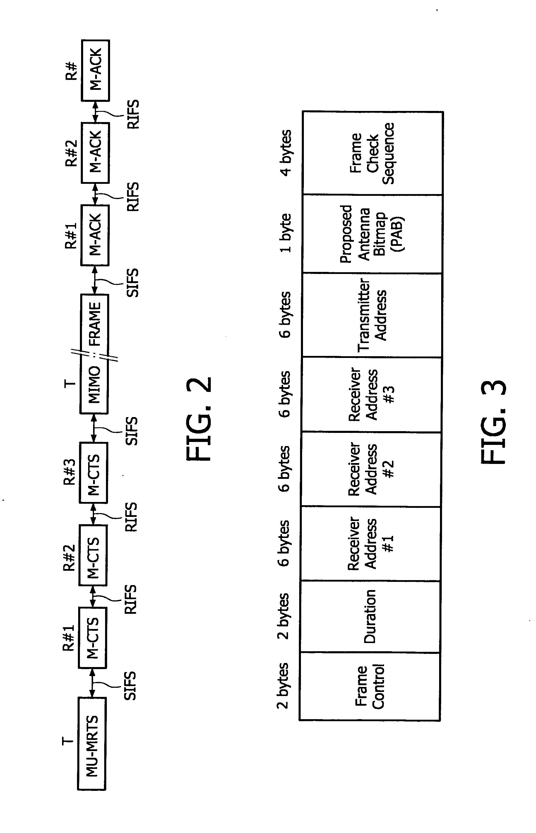
[0055]FIG. 2 shows a four-way handshake procedure according to a The proposed MU-DCF is based on the conventional M-DCF, wherein the four-way handshake procedure is proposed to facilitate channel access with multiple users prior to data transmission.

[0056]The following additional MAC protocol functionalities are proposed during a transmission cycle in MU MIMO scenarios, compared to the conventional M-DCF protocol.

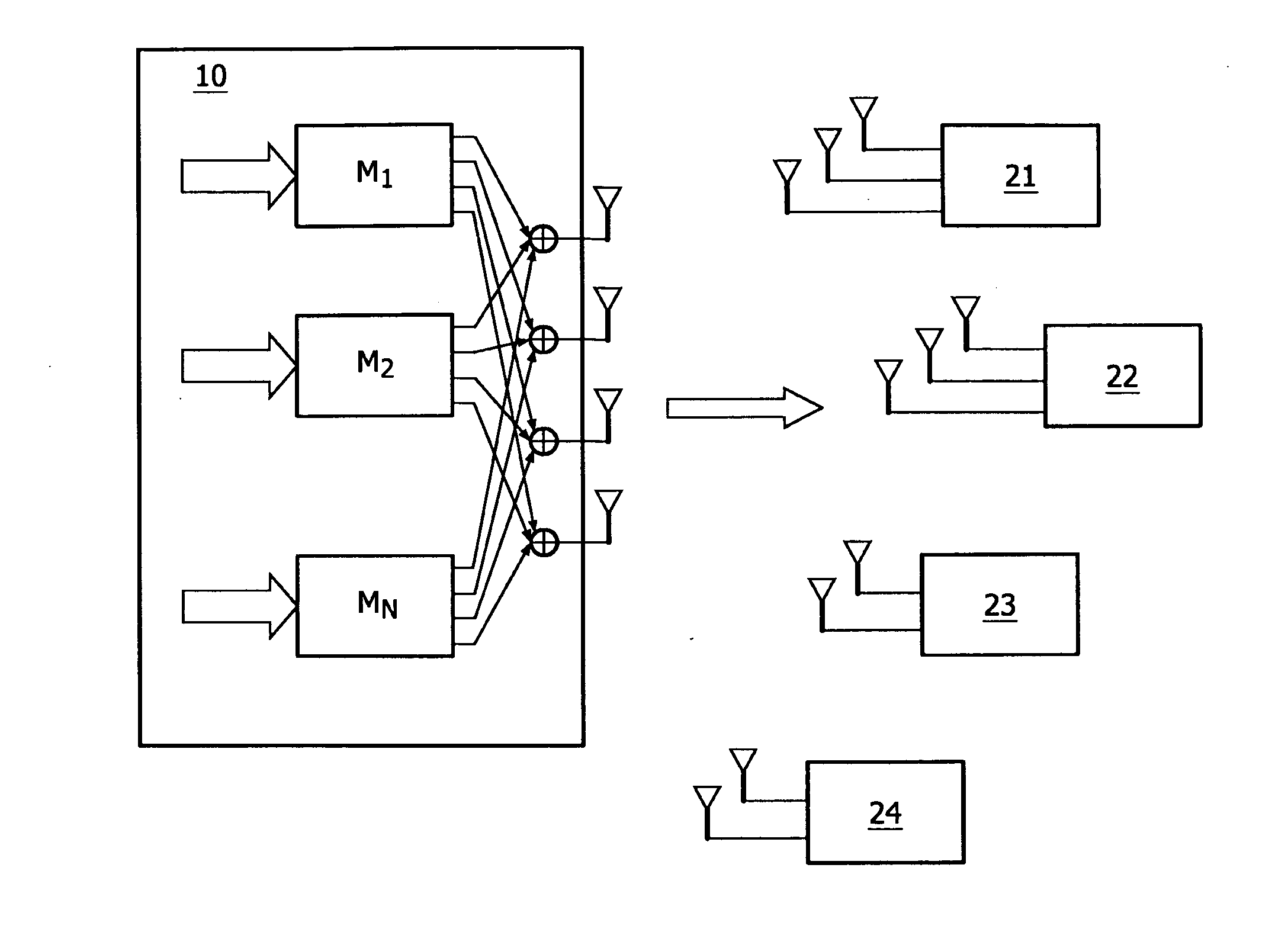
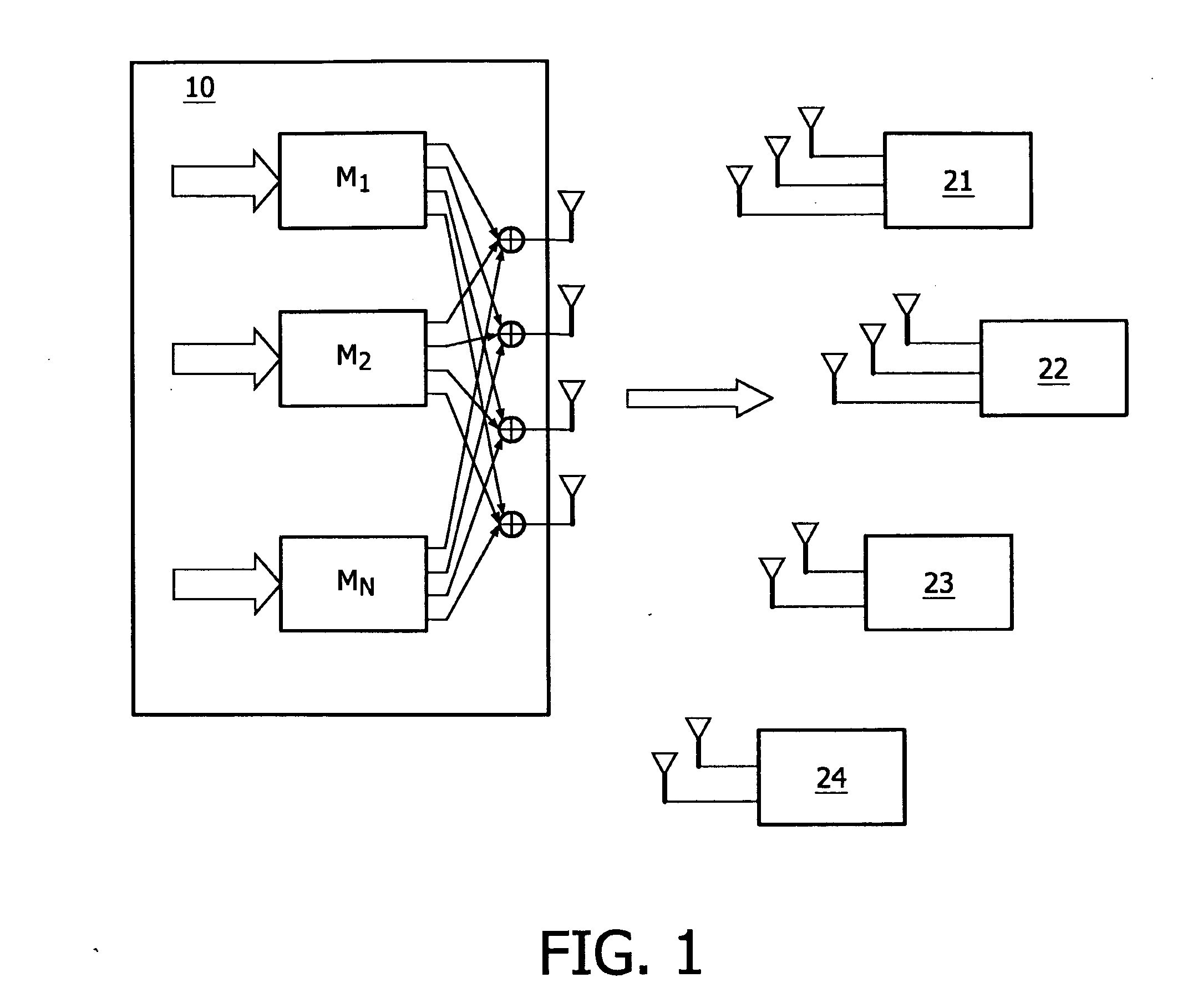
[0057]According to FIG. 2, the transmission is initiated e.g. by the AP 10 by broadcasting an MU-RTS frame as shown in FIG. 3 which is a MAC frame including multiple receiver addresses used for addressing e.g. three (R#1 to R#3) of the four exemplary stations 21 to 24 shown on FIG. 1. The MU-RTS frame can be followed by a training sequence for allowing channel estimation at the receiver side, e.g., at the selected ones of the stations 21 to 24. As an alternative option, channel estimation can also be done in parallel with the transmission of the MU-RTS frame, for example b...

second embodiment

[0077]In a second embodiment, a new MU-DCF with a two-phase channel access procedure is presented. A MU MIMO transmission is performed with beamforming support for IEEE 802.11 based networks by using MAC frames, such as MU-CFR, MIMO channel feedback (M-CF), MU-RTS and M-CTS frames, for accessing a channel, and a MAC frame M-ACK for acknowledging the correctly received packets. Optionally, an adaptive MU MIMO transmission may be performed by modifying the beamforming vectors for the MU MIMO transmission of only a subset of stations that replied with M-CTS to build the next MIMO frame. The decision can be made based on the information gained from the M-CTS frame. If the channels are already known, the MU-CFR and M-CF frames may not be necessary for the channel access mechanism of MU MIMO transmission.

[0078]MU MIMO transmission increases the spectral efficiency and provides a better utilization of resources. However, in MIMO systems, providing high throughput to multiple stations simul...

third embodiment

[0092]Because of the possibility that some stations polled for MU MIMO reception are not in each other communication range, it is proposed in the third embodiment that all stations polled for MU MIMO reception observe the end of the MU-RTS frame and calculate the duration they must wait before transmitting their M-CTS frames, taking into account the order of M-CTS transmission, the separation between each transmission, and the duration of each M-CTS transmission. A polled station then transmits its M-CTS frame after the determined duration (started from the time when the last transmission of an MU-RTS frame has been received by each station) has elapsed. While waiting to transmit the M-CTS frame, the concerned station does not need to sense the channel, because a correct reception of an MU-RTS frame implies a reserved channel between the station and the AP 10.

[0093]According to the third embodiment, the following improved procedure is proposed for setting up downlink MU MIMO transmi...


PUM


Abstract

The present invention relates to a transmitting apparatus, a receiving apparatus, a system and a method of performing multi-user transmission to a plurality of other transmission ends (21-24), wherein a request for transmission is broadcast to said plurality of other transmission ends (21-24), and the request is provided with a Medium Access Control MAC frame which includes a list of at least two identifications of receiving ends which are requested to reply to the request.

Description

FIELD OF THE INVENTION[0001]The present invention generally relates to a transmitting apparatus, a receiving apparatus, a system and a method of performing multi-user transmission to a plurality of other transmission ends in a transmission systems such as—but not restricted to—a wireless local area network (WLAN).BACKGROUND OF THE INVENTION[0002]Wireless local area networks (WLANs) as defined e.g. in the IEEE 802.11 specifications are almost omnipresent today. The increase of throughput of the available channel was one major issue, and research has been focused on improving the modulation and coding within the Physical Layer. By employing orthogonal frequency division multiplexing (OFDM) in combination with high-rate signal constellations, up to 54 Mbit / s could be achieved. This huge performance jump—even if achieved only for very limited distances—is caused by to inherent features of OFDM, which have become especially attractive for high bit-rate systems. In OFDM, the given system ...

Claims


Application Information

Patent Timeline
IPC IPC(8): H04J99/00
CPCH04L5/0023H04B17/309H04L5/0053H04L5/0094H04L25/0204H04L25/0224H04W8/26H04W28/06H04W72/1205H04W76/02H04W84/12H04B7/0452H04L1/0026H04B17/24H04L5/0046H04W76/10H04W72/12H04B7/0417H04B7/0626H04B7/2612
Inventor DENTENEER, THEODORUS JACOBUS JOHANNESREUMERMAN, HANSMIRKOVIC, JELENAWALKE, BERNARDEINHAUS, MICHAELSERBETLI, SEMIHHUSEN, SRI ANDARI
Owner KONINKLIJKE PHILIPS ELECTRONICS NV
Why Eureka
Try Eureka