Phase-locked loop circuit comprising voltage-controlled oscillator having variable gain
- Summary
- Abstract
- Description
- Claims
- Application Information
AI Technical Summary
Benefits of technology
Problems solved by technology
Method used
Image

Examples
embodiment
Configuration of a Phase-Locked Loop (PLL) Circuit
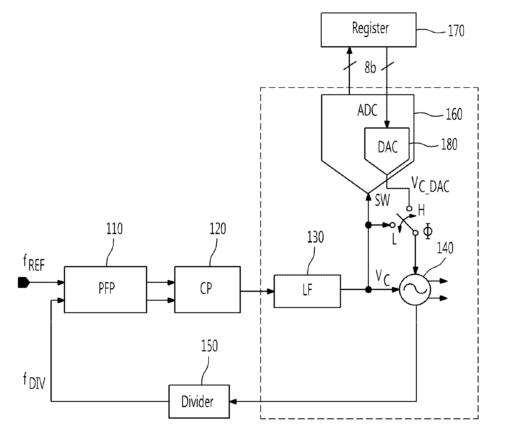
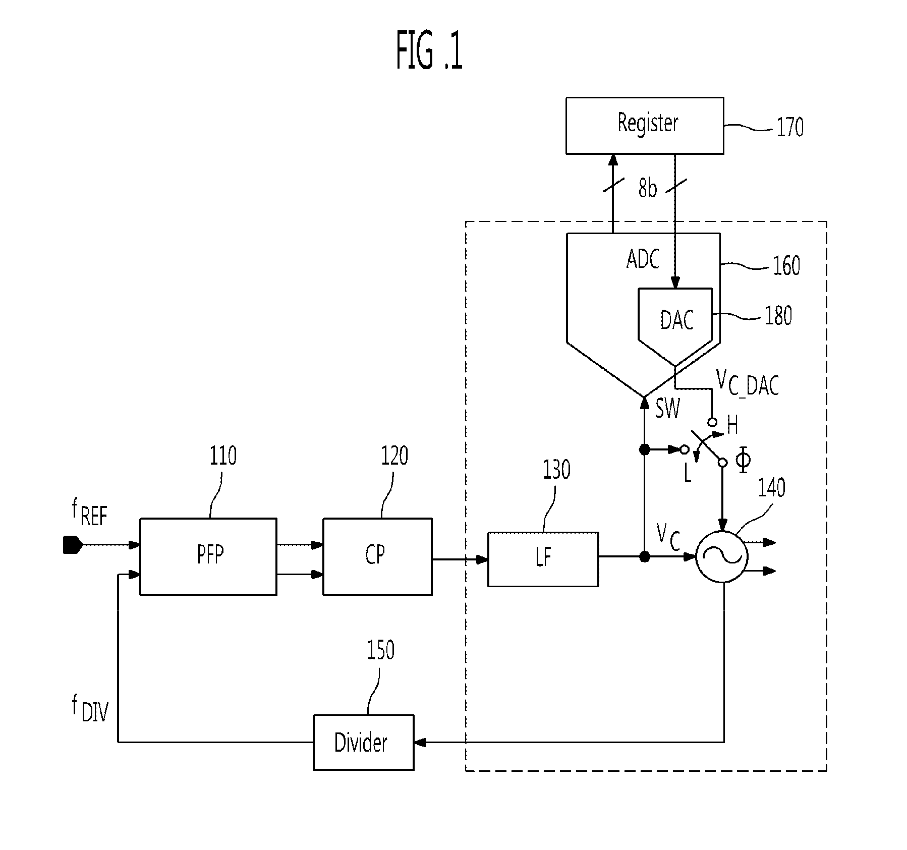
[0027]FIG. 1 is a block diagram of the entire configuration of a PLL circuit according to an exemplary embodiment of the present invention.
[0028]Referring to FIG. 1, a PLL circuit according to the present invention may have a basic loop including a phase frequency detector (PFD) 110, a charge pump (CP) 120, a loop filter (LF) 130, a voltage-controlled oscillator (VCO) 140, and a divider 150.
[0029]Also, the PLL circuit may further include an analog-to-digital converter (ADC) 160, a register 170, and a digital-to-analog converter (DAC) 180. The ADC 160 may receive an output voltage VC of the loop filter 130. The register 170 may store a digital code, which is an output value of the ADC 160. The DAC 180 may receive the digital code stored in the register 170.
[0030]Meanwhile, the PLL circuit may further include a switch SW, which may allow one of the output signal VC of the loop filter 130 and an output signal VC—DAC of the DAC 180 to be...
PUM
 Abstract
Description
Claims
Application Information
 - R&D
- Intellectual Property
- Life Sciences
- Materials
- Tech Scout
- Unparalleled Data Quality
- Higher Quality Content
- 60% Fewer Hallucinations
Browse by: Latest US Patents, China's latest patents, Technical Efficacy Thesaurus, Application Domain, Technology Topic, Popular Technical Reports.
© 2025 PatSnap. All rights reserved.Legal|Privacy policy|Modern Slavery Act Transparency Statement|Sitemap|About US| Contact US: help@patsnap.com