High electromagnetic transmission composite structure
a composite structure and electromagnetic wave technology, applied in the direction of waveguides, antenna details, antennas, etc., can solve the problems of increasing the loss of electromagnetic wave energy caused by spreading, the method of classifying radars is also complex, and the loss of electromagnetic wave energy will become more serious, so as to achieve effective reduction of transmission loss, strong structural strength, and wide effective operating frequency
- Summary
- Abstract
- Description
- Claims
- Application Information
AI Technical Summary
Benefits of technology
Problems solved by technology
Method used
Image
Examples
first embodiment
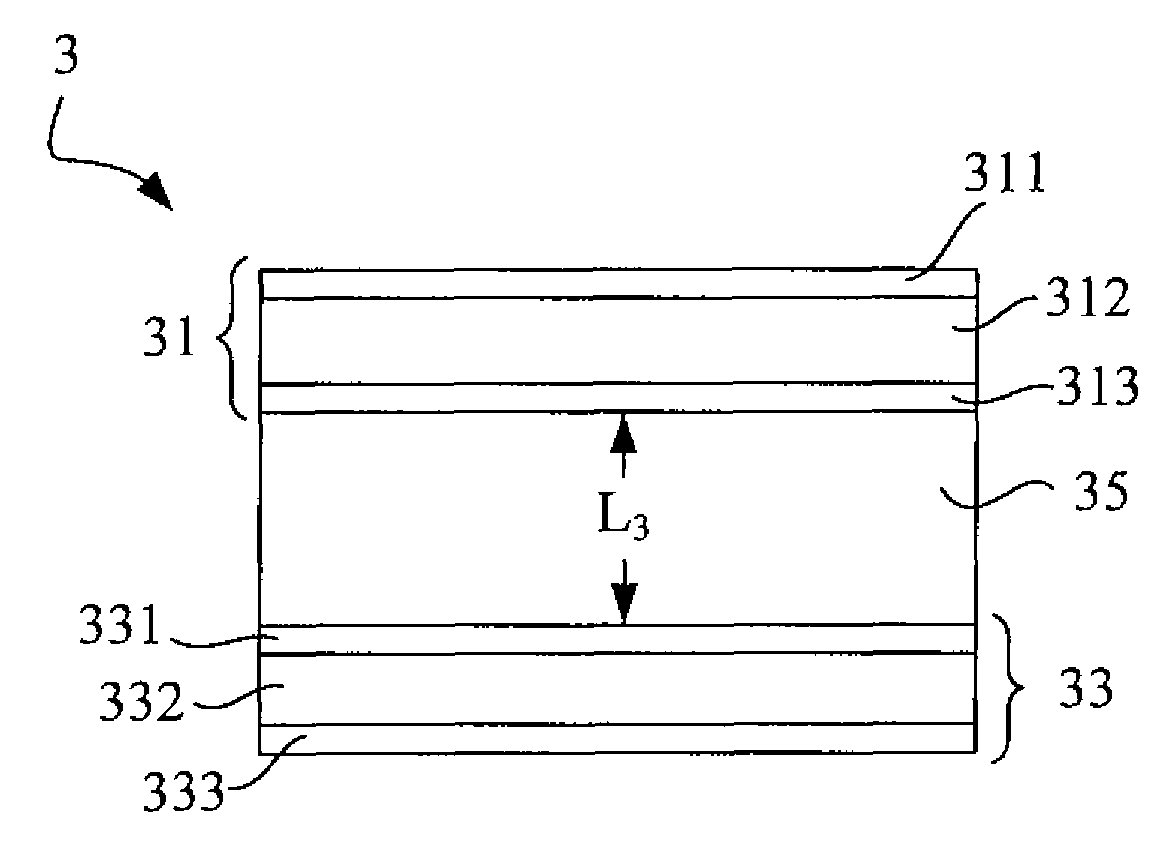
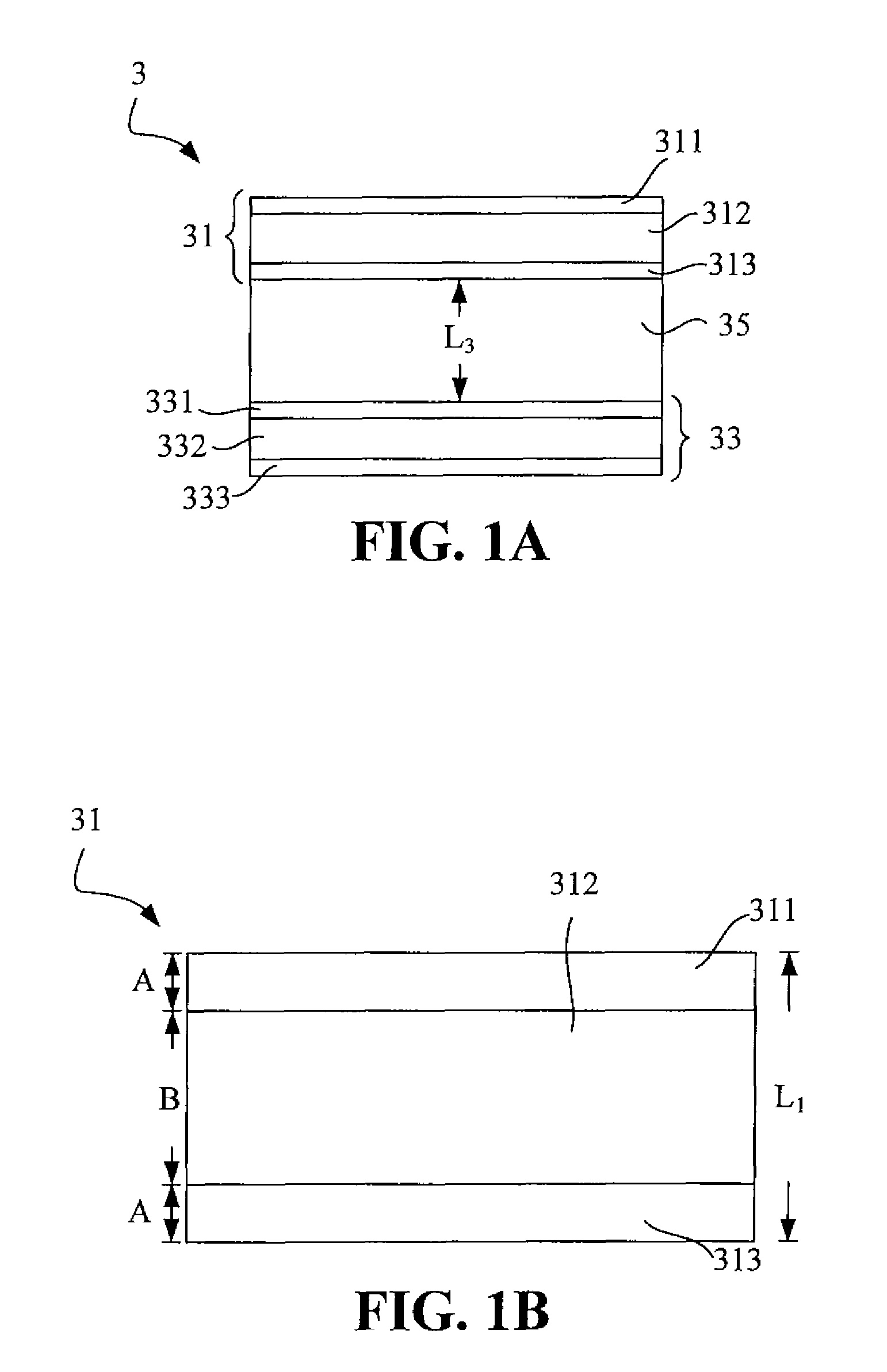
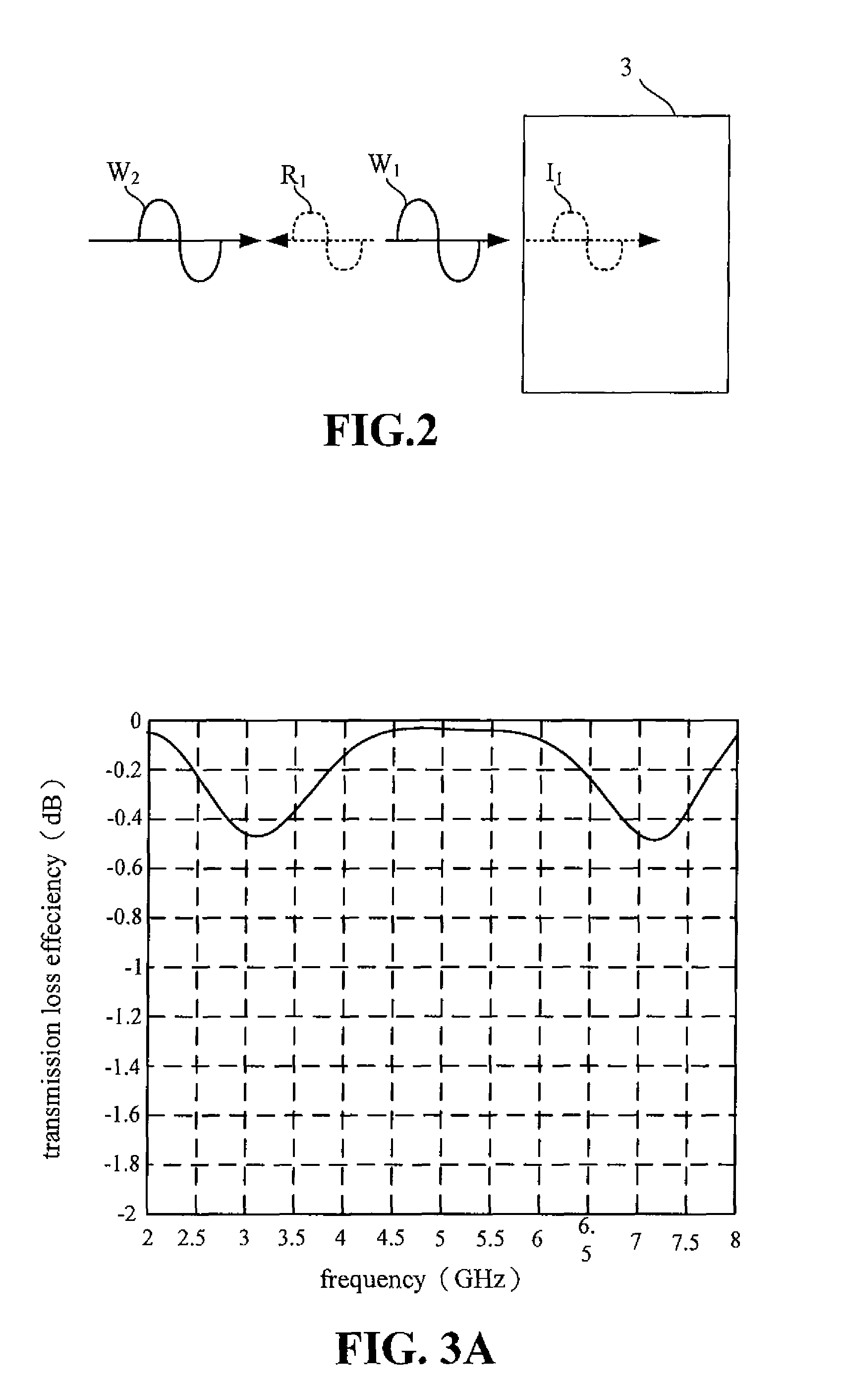
[0039]Please refer to FIG. 3A. FIG. 3A illustrates the analyzed result of the high electromagnetic transmission composite structure 3 of the invention. As shown in FIG. 3A, in the high electromagnetic transmission composite structure 3 of the invention in this embodiment, the thicknesses of the material layers are as follows: The thicknesses of the first composite board 311, the second composite board 313, the third composite board 331, and the fourth composite board 333 are all 1 mm, while the thicknesses of the first buffer layer 35, the second buffer layer 312, and the third buffer layer 332 are 30 mm, 10 mm, and 10 mm, respectively.
second embodiment
[0040]Please refer to FIG. 3B. FIG. 3B illustrates an analyzed result of the high electromagnetic transmission composite structure 3 of the invention. As shown in FIG. 3B, in the high electromagnetic transmission composite structure 3 of the invention in this embodiment, the thicknesses of the material layers are as follows: The thicknesses of the first composite board 311, the second composite board 313, the third composite board 331, and the fourth composite board 333 are all 1 mm, while the thicknesses of the first buffer layer 35, the second buffer layer 312, and the third buffer layer 332 are 45 mm, 10 mm, and 10 mm, respectively.
third embodiment
[0041]Please refer to FIG. 3C. FIG. 3C illustrates an analyzed result of the high electromagnetic transmission composite structure 3 of the invention. As shown in FIG. 3C, in the high electromagnetic transmission composite structure 3 of the invention in this embodiment, the thicknesses of the material layers are as follows: The thicknesses of the first composite board 311, the second composite board 313, the third composite board 331, and the fourth composite board 333 are all 1 mm, while the thicknesses of the first buffer layer 35, the second buffer layer 312, and the third buffer layer 332 are 60 mm, 10 mm, and 10 mm, respectively.
PUM
| Property | Measurement | Unit |
|---|---|---|
| dielectric constant E1 | aaaaa | aaaaa |
| dielectric constant E1 | aaaaa | aaaaa |
| dielectric constants E1 | aaaaa | aaaaa |
Abstract
Description
Claims
Application Information
 - R&D
- Intellectual Property
- Life Sciences
- Materials
- Tech Scout
- Unparalleled Data Quality
- Higher Quality Content
- 60% Fewer Hallucinations
Browse by: Latest US Patents, China's latest patents, Technical Efficacy Thesaurus, Application Domain, Technology Topic, Popular Technical Reports.
© 2025 PatSnap. All rights reserved.Legal|Privacy policy|Modern Slavery Act Transparency Statement|Sitemap|About US| Contact US: help@patsnap.com


