Flow rate measurement device

Active Publication Date: 2011-06-23
ORMON CORP
View PDF4 Cites 4 Cited by
  • Summary
  • Abstract
  • Description
  • Claims
  • Application Information

AI Technical Summary

Benefits of technology

[0012]A flow rate measurement device is not only used for measuring a flow rate of a dry gas like a gas meter for a city gas but also used in an environment where dew condensation water is easily generated or used together with an instrument storing a liquid.
[0016]The flow rate detection element is exposed in the detection flow passage for measuring flow speed of the gas. Thus, when the water flowing into the detection flow passage adheres onto the flow rate detection element, there is a fear that measurement precision of the flow rate detection element is lowered or the element itself is deteriorated. When the water does not adhere onto the flow rate detection element but the water breaking into the detection flow passage remains in the detection flow passage, a section area of the detection flow passage is changed, so that the flow speed of the gas passing through the detection flow passage is increased, and a diversion ratio of a main flow passage and the detection flow passage is also changed. Thus, the measurement precision of the flow rate measurement device is lowered.
[0020]One or more embodiments of the present invention provides a structure that a liquid does not easily adhere onto a flow rate detection element, and the liquid does not easily break into or remain in a detection flow passage in which the flow rate detection element is provided in a flow rate measurement device having a bypass flow passage structure for measuring a great flow rate.
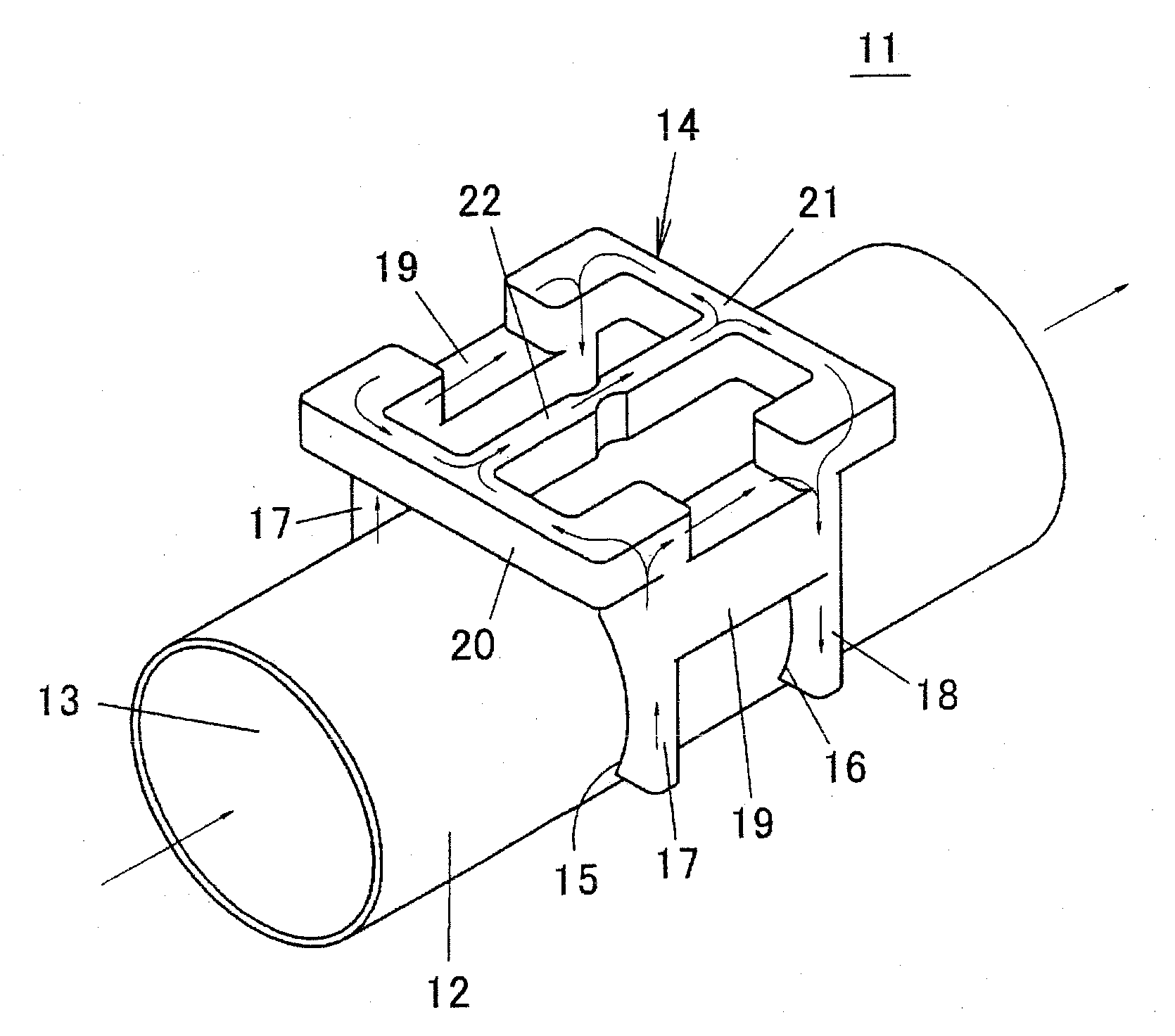
[0022]With the flow rate measurement device according to one or more embodiments of the present invention, the upstream end of the detection flow passage is positioned on the upstream side of the main flow passage relative to the both ends of the upstream auxiliary flow passage, and the downstream end of the detection flow passage is positioned on the downstream side of the main flow passage relative to the both ends of the downstream auxiliary flow passage. Thus, even when an instrument in which the flow rate measurement device is built falls down and the flow rate measurement device is vertically placed or lies on the side, a liquid does not easily breaks into the detection flow passage, so that the detection flow passage is not easily contaminated by the liquid and the liquid does not easily adhere onto the flow rate detection element. Therefore, even in a case where the flow rate measurement device is built in an instrument using the liquid, characteristics of the flow rate measurement device are not easily lowered even with the liquid breaking into the flow rate measurement device.
[0023]In a flow rate measurement device according to one or more embodiments of the present invention, the upstream end of the detection flow passage is connected to the upstream auxiliary flow passage at a position away from the downstream ends of the introduction flow passages, and the downstream end of the detection flow passage is connected to downstream auxiliary flow passage at a position away from the upstream ends of the discharge flow passages. With such an arrangement, the upstream auxiliary flow passage or the downstream auxiliary flow passage is placed between the introduction flow passages or the discharge flow passages and the detection flow passage. Thus, the liquid breaking into the introduction flow passages or the discharge flow passages can be prevented from directly flowing into the detection flow passage.
[0027]In a flow rate measurement device according to one or more embodiments of the present invention, the auxiliary flow passage has a symmetric structure relative to a plane passing through center of the flow rate detection element, the plane being perpendicular to the axial direction of the main flow passage. With such an arrangement, a flow of the gas in the auxiliary flow passage can be stabilized.

Problems solved by technology

Thus, downsizing of the device is limited.
However, in such a flow rate measurement device having the bypass flow passage structure, flow speed distribution on a vertical section in the main flow passage easily becomes inhomogeneous due to existence of the auxiliary flow passage.
When the flow speed distribution in the main flow passage is inhomogeneous, the diversion ratio to the auxiliary flow passage becomes unstable.
Thus, a precise total flow rate is not easily determined.
In such equipment, a great flow rate of the gas has to be measured, and furthermore, downsizing is required, and the flow passages are required to have low pressure loss for using a small-power mechanical power source.
Thus, when the water flowing into the detection flow passage adheres onto the flow rate detection element, there is a fear that measurement precision of the flow rate detection element is lowered or the element itself is deteriorated.
Further, in the flow rate measurement device of Patent Document 2, since the introduction flow passages and the discharge flow passages are arranged in all directions of center of the main flow passage, a water discharge property due to gravity is unfavorable.
Thus, once the water breaks into the introduction flow passages, the discharge flow passages, or the detection flow passage, the water is not easily discharged.
Therefore, a flow rate measurement device having a structure that the gas can pass through the detection flow passage but the liquid does not easily break into the detection flow passage is desired.
Thus, even when an instrument in which the flow rate measurement device is built falls down and the flow rate measurement device is vertically placed or lies on the side, a liquid does not easily breaks into the detection flow passage, so that the detection flow passage is not easily contaminated by the liquid and the liquid does not easily adhere onto the flow rate detection element.
Therefore, even in a case where the flow rate measurement device is built in an instrument using the liquid, characteristics of the flow rate measurement device are not easily lowered even with the liquid breaking into the flow rate measurement device.
Thus, the liquid does not easily break into the detection flow passage.
Thus, the liquid does not easily flow to the detection flow passage through the upstream flow passage and the downstream flow passage.

Method used


Image

  • Flow rate measurement device
  • Flow rate measurement device
  • Flow rate measurement device

Examples


first embodiment

[0042]Hereinafter, a structure of a flow rate measurement device according to a first embodiment of the present invention will be described with reference to FIGS. 3 to 7. FIG. 3 is an exploded perspective view of a flow rate measurement device 41 according to the first embodiment. FIG. 4 is a partially-broken perspective view of a base member of the flow rate measurement device 41. FIG. 5 is a plan view of the base member, FIG. 6 is a sectional view by the line X-X of FIG. 5, and FIG. 7 is a sectional view by the line Y-Y of FIG. 5.

[0043]As shown in FIG. 3, the flow rate measurement device 41 of the first embodiment includes a synthetic resin base member 45 formed by integrating an auxiliary flow passage block 44 for forming an auxiliary flow passage on an outer peripheral surface of a main flow pipe 42, an annular seal member 46 made of an insulating material such as rubber, and a circuit substrate 48 in which a flow rate detection element 47 is mounted on a lower surface.

[0044]A ...

second embodiment

[0079]FIG. 12 is a plan view of a base member 81 used in the flow rate measurement device according to a second embodiment of the present invention. In this embodiment, the left and right first auxiliary flow passages 58 in the first embodiment are omitted, and the introduction ports 54 and the discharge ports 55 are not directly connected to each other. With such a structure, since the gas does not flow to the first auxiliary flow passages, the flow rate in the detection flow passage 61 can be increased. In this embodiment, the bottom surface of the measurement chamber 62 is not raised, and the bottom surface of the detection flow passage 61 is formed to be flat from one end to the other end.

third embodiment

[0080]FIG. 13 is a sectional view of a flow rate measurement device 91 according to a third embodiment of the present invention. In this flow rate measurement device 91, left and right symmetrical surfaces of the auxiliary flow passage are displaced from left and right symmetrical surfaces of the main flow passage 43. With such a structure, since the two introduction ports 54 are provided at asymmetrical positions of the main flow passage 43, a function of averaging the flow speed of the measurement gas sampled from the introduction ports 54 is promoted.

[0081]While the invention has been described with respect to a limited number of embodiments, those skilled in the art, having benefit of this disclosure, will appreciate that other embodiments can be devised which do not depart from the scope of the invention as disclosed herein. Accordingly, the scope of the invention should be limited only by the attached claims.


PUM


Abstract

A flow rate measurement device has a main flow pipe having a main flow passage through which a gas passes, an orifice for limiting a flow of the gas in the main flow passage, and an auxiliary flow passage block provided with an auxiliary flow passage having one end communicating with a pair of introduction ports opened in the main flow passage on the upstream side of the orifice and the other end communicating with a pair of discharge ports opened in the main flow passage on the downstream side of the orifice. The auxiliary flow passage includes a pair of introduction flow passages having upstream ends respectively communicating with the introduction ports, an upstream auxiliary flow passage having both ends respectively connected to downstream ends of the introduction flow passages, and a pair of discharge flow passages having downstream ends respectively communicating with the discharge ports.

Description

BACKGROUND OF THE INVENTION[0001]1. Technical Field[0002]The present invention relates to a flow rate measurement device for measuring a flow rate of a gas, for example to a flow rate measurement device used in medical instruments such as treatment equipment for sleep apnea syndrome, industrial instruments for monitoring an air flow rate in factories, use in instrument embedment, and the like.[0003]2. Background Art[0004]In general, in a straight pipe type flow rate measurement device for directly measuring a great flow rate among flow rate measurement devices, there is a need for enlarging a diameter of a pipe in order to lower flow speed by a measurable area of a flow rate detection element. Thus, downsizing of the device is limited. In order to downsize the flow rate measurement device for measuring a great flow rate, in general, a flow rate measurement device having a bypass flow passage structure is proposed. In the flow rate measurement device having the bypass flow passage st...

Claims


Application Information

Patent Timeline
IPC IPC(8): G01F5/00
CPCG01F5/00G01F1/6842G01F1/68G01F1/684
Inventor UEDA, NAOTSUGUNOZOE, SATOSHI
Owner ORMON CORP
Why Eureka
Try Eureka