Flow measuring device

Active Publication Date: 2011-01-06
ORMON CORPORATION
View PDF8 Cites 3 Cited by
  • Summary
  • Abstract
  • Description
  • Claims
  • Application Information

AI Technical Summary

Benefits of technology

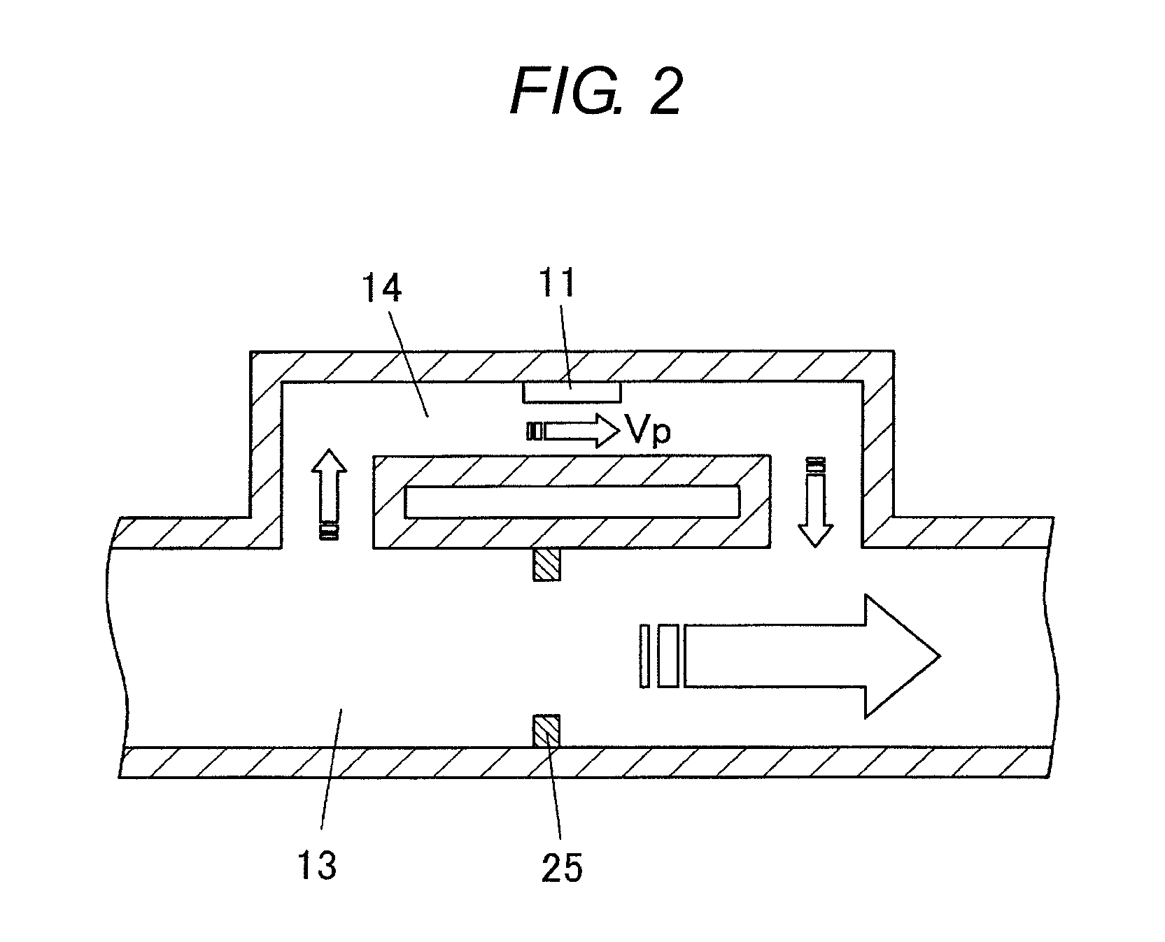
[0016]The displacement of the positions of the vent hole 33 and the inlet 23 in this manner gives an influence on the flow of the gaseous body that flows from the main flow channel 13 into the auxiliary flow channel 14, and thus can produce variation in the flow ratio between the main flow channel 13 and the auxiliary flow channel 14, thereby causing the decrease of the measurement accuracy of the flow measuring device.
[0034]Moreover, according to this aspect, a resilient member can be sandwiched between the end surface of the orifice holding member and the end cap. By sandwiching the resilient member between the end surface of the orifice holding member and the end cap, it is possible to press the orifice holding member against the orifice by the resilient repulsion of the resilient member, thereby securely holding the orifice.

Problems solved by technology

As a result, preparing flow measuring devices of flow amount ranges for various purposes becomes expensive and requires a large storage space.
However, even with this method, a stepped section was generated between the vent hole 33 and the inlet 23, and the flow of the gaseous body directed to the auxiliary flow channel 14 was disturbed by this stepped section, and thus it was not possible to reduce the variation of the flow ratio.

Method used


Image

  • Flow measuring device
  • Flow measuring device
  • Flow measuring device

Examples


first embodiment

Modified Examples of First Embodiment

[0085]FIG. 18 is a cross-sectional view illustrating a modified example of the first embodiment. According to a flow measuring device 91, as compared to the case of the first embodiment, the distance between the orifice supporting spacer 65 and the flow channel wall 54 is slightly decreased, and the end surface of the orifice supporting spacer 65 and the end surface of the flow channel wall 54 are slightly recessed from the front end surface of the main flow channel portion 55a. Then, a resilient members 92 such as an O-ring is sandwiched between the end surface of the orifice supporting spacer 65 and the end surface of the flow channel wall 54 and the back surface of the end cap 68, thereby press-tightening the resilient member 92. According to this modified example, as the orifice supporting spacer 65 can be pressed against the orifice 63 by resilient repulsion of the resilient member 92, it is possible to make the orifice 63 to be held without...

second embodiment

[0094]FIG. 23 is a cross-sectional view illustrating a flow measuring device 101 according to a second embodiment of the present invention. FIG. 24 is a partially broken perspective view illustrating the flow channel block 52 that is used for the flow measuring device 101. FIG. 25A is a perspective view illustrating the orifice supporting spacer 65 that is used for the flow measuring device 101.

[0095]According to the flow measuring device 101, as shown in FIG. 25A, the cut-out section 66 is formed not along the entire orifice supporting spacer 65 such that the cut-out section 66 is shorter than the orifice supporting spacer 65. On the other hand, as shown in FIG. 24, within the main flow channel 53 of the flow channel block 52, leaving the flow channel wall 54 having the same shape and size as the cut-out section 66, the spacer container 74 is formed at the remaining area. The branch entrance 72a opens in the flow channel wall 54, and a distance sufficient for not influencing the fl...

third embodiment

Modified Examples of Third Embodiment

[0100]FIG. 27 is a partially broken perspective view illustrating a modified example of the third embodiment. According to a flow measuring device 103, each of the front and back orifice supporting spacers 65 is formed by a number of short orifice supporting spacers 65c. It is desirable to use the orifice supporting spacers 65c of the same length.

[0101]According to this modified example, it is possible to freely change the position of the orifice 63 depending on a gap out of gaps between the orifice supporting spacers 65c in which the orifice 63 is inserted, thereby adjusting the flow ratio. It should be noted that such as a gas flow straightener can be sandwiched between the orifice supporting spacers 65c.


PUM


Abstract

A flow measuring device has a flow channel block including a main flow channel whose both ends are open, and an auxiliary flow channel that branches from the main flow channel, a flow amount measurement element provided for the auxiliary flow channel, and a branch entrance and a collection exit that open in a wall surface of the main flow channel, and that communicate to the auxiliary flow channel, so that a part of a gaseous body that flows through the main flow channel is directed to the auxiliary flow channel through the branch entrance, and the gaseous body that has passed through the auxiliary flow channel is directed back to the main flow channel through the collection exit. A holding member containing portion is provided in a depressed manner for an area excluding an area including the branch entrance and an area including the collection exit in a circumference surface of a space of the flow channel block that configures the main flow channel. An orifice is contained within the main flow channel. An orifice holding member fitted into the holding member containing portion holds the orifice by being brought into contact with the orifice. The wall surface of the main flow channel is configured by a wall surface excluding the area for which the holding member containing portion is formed out of the main flow channel and an inner surface of the orifice holding member.

Description

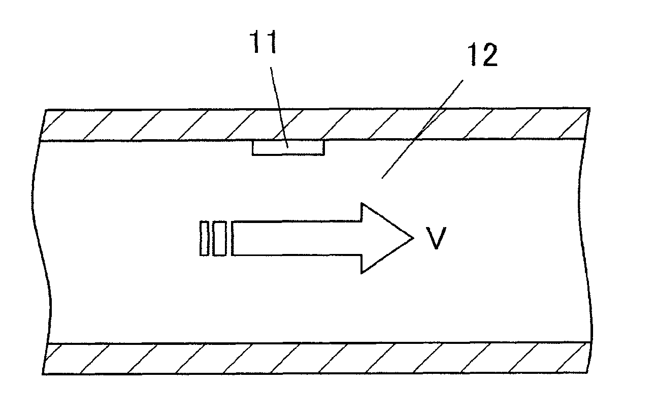
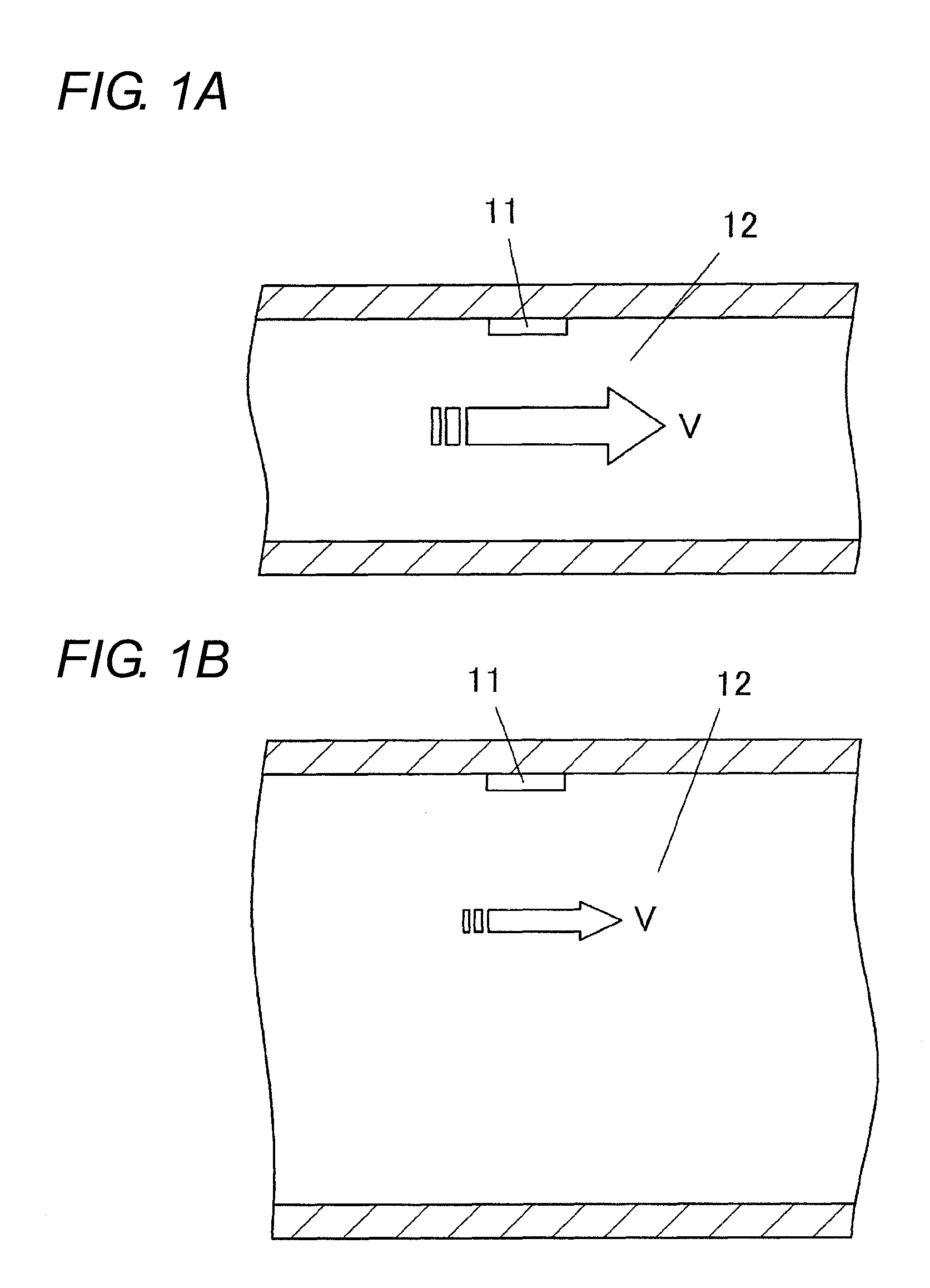
BACKGROUND OF THE INVENTION[0001]1. Technical Field[0002]The present invention relates to flow measuring devices, in particular, to a flow measuring device for measuring a flow amount of a gaseous body.[0003]2. Related Art[0004]A straight-tube type flow measuring device typically measures a flow velocity V of a gaseous body that flows through a flow channel 12 using a flow detection element 11, as shown in FIG. 1A or 1B, and measures a flow amount of the gaseous body within the flow channel 12 based on the measured flow velocity V and a flow channel cross-sectional area.[0005]When a certain amount of the gaseous body flows through the flow channel 12 in the flow measuring device having such a structure, the flow velocity V of the gaseous body increases if the flow channel cross-sectional area is small as shown in FIG. 1A, and the flow velocity V of the gaseous body decreases if the flow channel cross-sectional area is large as shown in FIG. 1B. On the other hand, the flow detection ...

Claims


Application Information

Patent Timeline
IPC IPC(8): G01F1/42
CPCG01F1/6845G01F5/005G01F1/6842G01F1/42G01F1/684G01F15/185
Inventor UEDA, NAOTSUGUYAMAMOTO, KATSUYUKIMAEDA, SHUJITSUJI, YUJI
Owner ORMON CORPORATION
Why Eureka
Try Eureka