
Method and apparatus for hybrid virtual MIMO transmission in wireless ad-hoc network

a wireless ad-hoc network and hybrid technology, applied in the field of hybrid virtual mimo transmission can solve the problems of affecting the implementation of mimo routing, consuming a large amount of energy, and difficult to employ mimo routing in wireless ad-hoc network, so as to achieve maximum energy efficiency and limited energy

Active Publication Date: 2011-06-16
ELECTRONICS & TELECOMM RES INST +1
View PDF2 Cites 13 Cited by
  • Summary
  • Abstract
  • Description
  • Claims
  • Application Information

AI Technical Summary

Benefits of technology

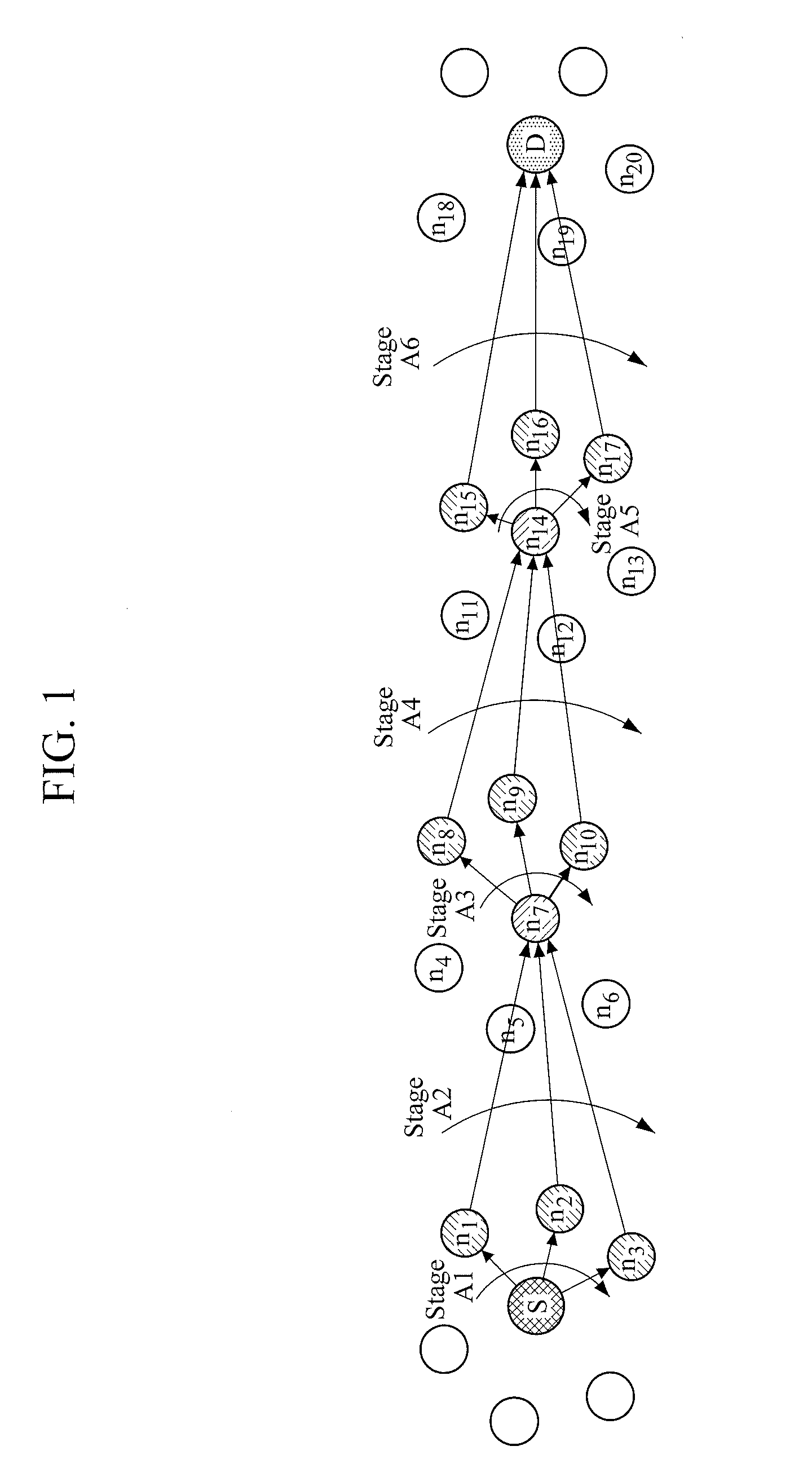
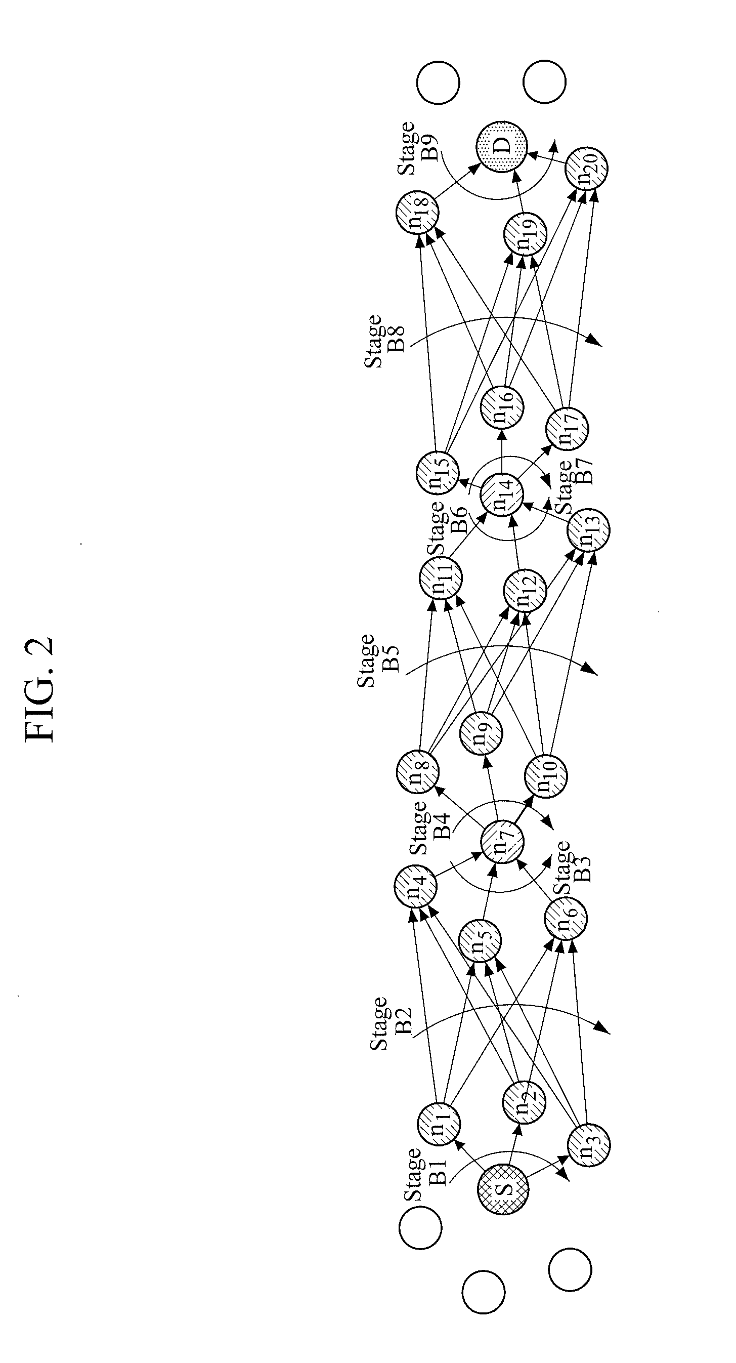
[0008]The following description relates to a multiple-input multiple-output (MIMO) transmission apparatus and method which can maximize energy efficiency under a wireless ad-hoc network multiple-hop transmission environment which has limited energy.
[0009]In addition, provided are a MIMO transmission apparatus and method which satisfy quality of service (QoS) while taking energy efficiency into consideration to reduce a transmission delay time between a source node and a destination node.

Problems solved by technology

However, for MIMO routing, a transmitter and a receiver are configured to have a complex circuit structure, which consumes a great amount of energy, and the MIMO routing is difficult to employ in a wireless ad-hoc network.
Moreover, numerous antennas must be installed in a small sensor for MIMO routing, and such installation hinders the implementation of the MIMO routing.
An ad-hoc network employing V-MIMO has an advantage of multiplexing gain that is retained by MIMO transmission, but has a disadvantage in that extra energy is required for cooperation between sensors participating in routing and transmission delay.
Thus, in the case of short data transmission distance, the V-MIMO is not efficient in terms of energy and delay time.

Method used


Image

  • Method and apparatus for hybrid virtual MIMO transmission in wireless ad-hoc network
  • Method and apparatus for hybrid virtual MIMO transmission in wireless ad-hoc network
  • Method and apparatus for hybrid virtual MIMO transmission in wireless ad-hoc network

Examples


Embodiment Construction

G. 16 is a diagram illustrating an example of an RN which operates in a distributed hybrid routing environment.

[0026]FIG. 17 is a diagram illustrating an example of a CN which operates in a distributed hybrid routing environment.

[0027]FIGS. 18 to 22 are examples of graphs showing changes in a routing path.

[0028]Throughout the drawings and the detailed description, unless otherwise described, the same drawing reference numerals will be understood to refer to the same elements, features, and structures. The relative size and depiction of these elements may be exaggerated for clarity, illustration, and convenience.

DETAILED DESCRIPTION

[0029]The following description is provided to assist the reader in gaining a comprehensive understanding of the methods, apparatuses, and / or systems described herein. Accordingly, various changes, modifications, and equivalents of the methods, apparatuses, and / or systems described herein will be suggested to those of ordinary skill in the art. Also, descr...


PUM


Abstract

A hybrid virtual multiple-input multiple-output (V-MIMO) transmission method of a management node in a wireless ad-hoc network in which a transmission path from a source node to a destination node is divided into one or more sections is provided. The hybrid V-MIMO transmission method includes obtaining one or more pieces of node information of one or more nodes by transmitting an information request message to the nodes in response to a transmission request message for data transmission from the source node to the destination node; setting a shortest path (SP) from the source node to the destination node based on the obtained node information; determining transmission schemes individually for nodes present on the SP; issuing a transmission preparation request by transmitting the determined transmission schemes to the respective corresponding nodes; and transmitting a transmission start message to the source node in response to transmission ready responses from the respective nodes.

Description

CROSS-REFERENCE TO RELATED APPLICATION(S)[0001]This application claims the benefit under 35 U.S.C. §119(a) of a Korean Patent Application Nos. 10-2009-0125133, filed on Dec. 15, 2009, and 10-2010-0045499, filed on May 14, 2010, in the Korean Intellectual Property Office, the entire disclosures of which are incorporated herein by references for all purposes.BACKGROUND[0002]1. Field[0003]The following description relates to a method and apparatus for multiple input multiple output (MIMO) routing, and more particularly, to a method and apparatus for hybrid virtual MIMO transmission in a wireless ad-hoc network.[0004]2. Description of the Related Art[0005]Various multiple-input multiple-output (MIMO) transmission techniques have been developed utilizing the nature of high bandwidth efficiency of the MIMO transmission scheme. However, for MIMO routing, a transmitter and a receiver are configured to have a complex circuit structure, which consumes a great amount of energy, and the MIMO ro...

Claims


Application Information

Patent Timeline
Patent Type & Authority Applications(United States)
IPC IPC(8): H04L27/00
CPCH04B7/024H04L5/0023H04L5/0035Y02B60/50H04W40/06H04W40/10H04W40/20H04L45/121Y02D30/70
Inventor JEONG, WUN-CHEOLCHUNG, JONG-MOONKIM, JOON-HYUNGHAN, DONG-HYUKJOO, SEONG-SOONCHAE, JONG-SUK
Owner ELECTRONICS & TELECOMM RES INST
Learn More