Electromagnetic shielding for camera modules

a technology of electromagnetic shielding and camera modules, applied in the direction of magnets, television systems, magnetic bodies, etc., can solve the problems of reducing the overall energy, affecting the correct operation of electronic devices, and affecting the performance of electronic components

Active Publication Date: 2011-06-02
STMICROELECTRONICS (RES & DEV) LTD
View PDF11 Cites 42 Cited by
  • Summary
  • Abstract
  • Description
  • Claims
  • Application Information

AI Technical Summary

Benefits of technology

[0017]The conductive coating may be selectively applied so that the part of the component to whose surface the conductive coating is applied, that is for bonding to the substrate, may be kept free from the conductive coating. The conductive coating may be selectively applied so that part or parts of the component to whose surface the conductive coating is applied that may include electrical contacts may be kept free from conductive coating.

Problems solved by technology

Unwanted electromagnetic fields can interfere with the correct operation of the electronic devices.
As well as being sensitive to EMI, electronic devices can also generate EMI that can degrade the performance of the devices themselves, or of other electronic components.
This may not reduce the overall energy of the emitted EMI, but it may reduce unwanted peaks, which would block frequency channels for data communication or other purposes.
However, a metal may add significant weight and bulk to the overall assembly.
The forming process for manufacturing a metal may have a relatively poor yield, and the design of components within the module, such as, lens actuators, and so on, may have to take into account the specific structure of the metal can in advance, in the design process.
The connection to ground of the metal may also present problems, as it may rely on metallized sockets, or, in the case of flexed camera modules, a more complicated grounding chain, which may have poor reliability.
Electroplating is relatively expensive to apply and often requires multiple passes of a plating applicator to achieve satisfactory coating.
The electroplated coatings may be easily scratched or damaged during handling, which may result in visual defects and foreign matter causing optical occlusion or electrical shorting.
Conductive paint is relatively cheaper to apply, however, the masking of the paint may present issues, and consistent application may be difficult.
Use of conductive paint may also involve an additional curing process, adding time and expense to the manufacturing process.
The weaker signals and sensitive antennas mean that unwanted EMI has a greater effect on the signal quality for voice and data calls.

Method used


Image

  • Electromagnetic shielding for camera modules
  • Electromagnetic shielding for camera modules
  • Electromagnetic shielding for camera modules

Examples


Embodiment Construction

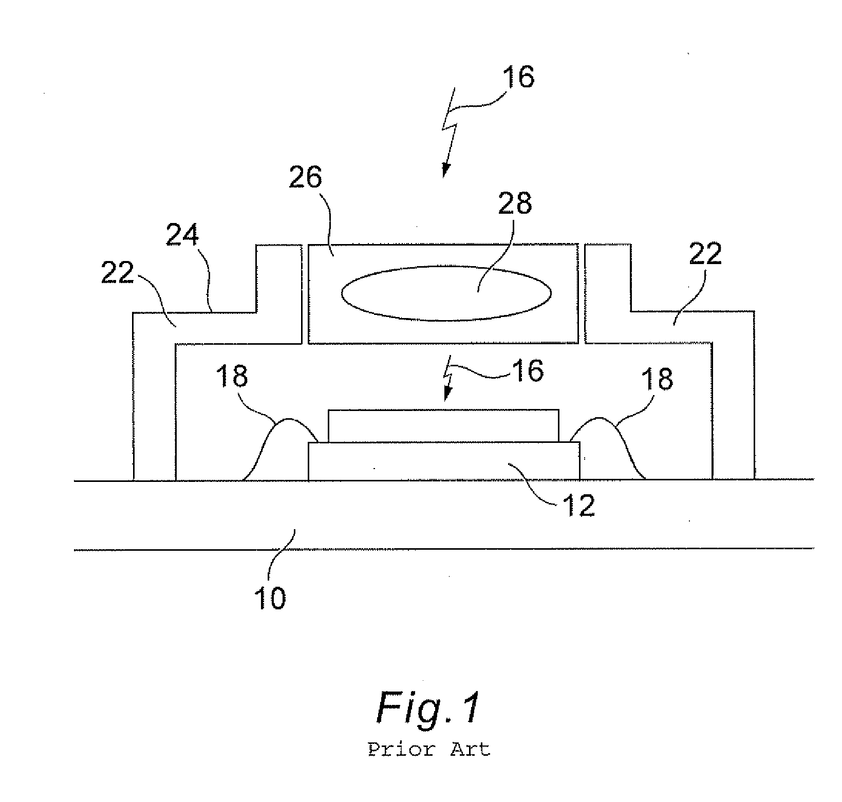
[0031]FIG. 1 shows a typical camera module. Selected components are shown for ease of illustration in the present disclosure, and it is to be understood that other components may be incorporated into the structure. An imaging die 12 is assembled on a substrate 10. The substrate 10 could be a PCB, ceramic, or other material. The imaging die 12 comprises a radiation sensitive portion, which collects incident radiation 16. For an image sensor the radiation sensitive portion will usually be photosensitive, and the incident radiation 16 will usually be light including light in the (human) visible wavelength ranges, as well as, perhaps, infrared and ultraviolet. Bond wires 18 are provided for forming electrical connections with the substrate 10. Other electrical connections are possible, such as solder bumps, for example. A number of electrical components are formed in the body of the imaging die 12 and / or the substrate 10. These components may control the image sensing and readout operat...


PUM

PropertyMeasurementUnit
electrical conductoraaaaaaaaaa
conductiveaaaaaaaaaa
electricalaaaaaaaaaa

Abstract

A camera module may include a substrate, and an image sensor mounted on the substrate. The camera module may also include a housing, and an electromagnetic interference (EMI) shield provided around the image sensor and within the module. The camera module may be particularly suited for use in a mobile telephone, for example.

Description

FIELD OF THE INVENTION[0001]The present disclosure relates to electromagnetic shielding for camera modules.BACKGROUND OF THE INVENTION[0002]Digital image sensing based upon solid state technology is known. The two most common types of image sensors currently may be charge coupled devices (CCDs) and complementary metal oxide semiconductor (CMOS) image sensors. Digital image sensors may be incorporated within a wide variety of devices throughout the consumer, industrial, defence, and other sectors.[0003]An image sensor is a device that may comprise one or more radiation sensitive elements having an electrical property that changes when radiation is incident upon them, together with circuitry for converting the changed electrical property into a signal. As an example, an image sensor may comprise a photodetector that generates a charge when radiation is incident upon it. The photodetector may be sensitive to electromagnetic radiation in the range of (human) visible wavelengths, or othe...

Claims


Application Information

Patent Timeline
Patent Type & Authority Applications(United States)
IPC IPC(8): H04M1/00H04N5/225H05K13/00
CPCH01L27/14618H01L27/14621Y10T29/4902H01L27/14625H04N5/2257H01L27/14623H01L2224/48091H01L2224/48227H04N23/57H01L2924/00014H01L2924/0002H01L2924/00
Inventor HALLIDAY, WILLIAM
Owner STMICROELECTRONICS (RES & DEV) LTD
Why Eureka
Try Eureka