
Photonic biosensor, photonic biosensor array, and method of detecting biomaterials using the same

a biosensor and photonic technology, applied in the field of photonic biosensors, can solve the problems of increasing the fabrication cost of biosensors, complex process, increasing process costs, etc., and achieve the effect of facilitating the detection of biomaterials

Inactive Publication Date: 2011-06-02
ELECTRONICS & TELECOMM RES INST
View PDF12 Cites 9 Cited by
  • Summary
  • Abstract
  • Description
  • Claims
  • Application Information

AI Technical Summary

Benefits of technology

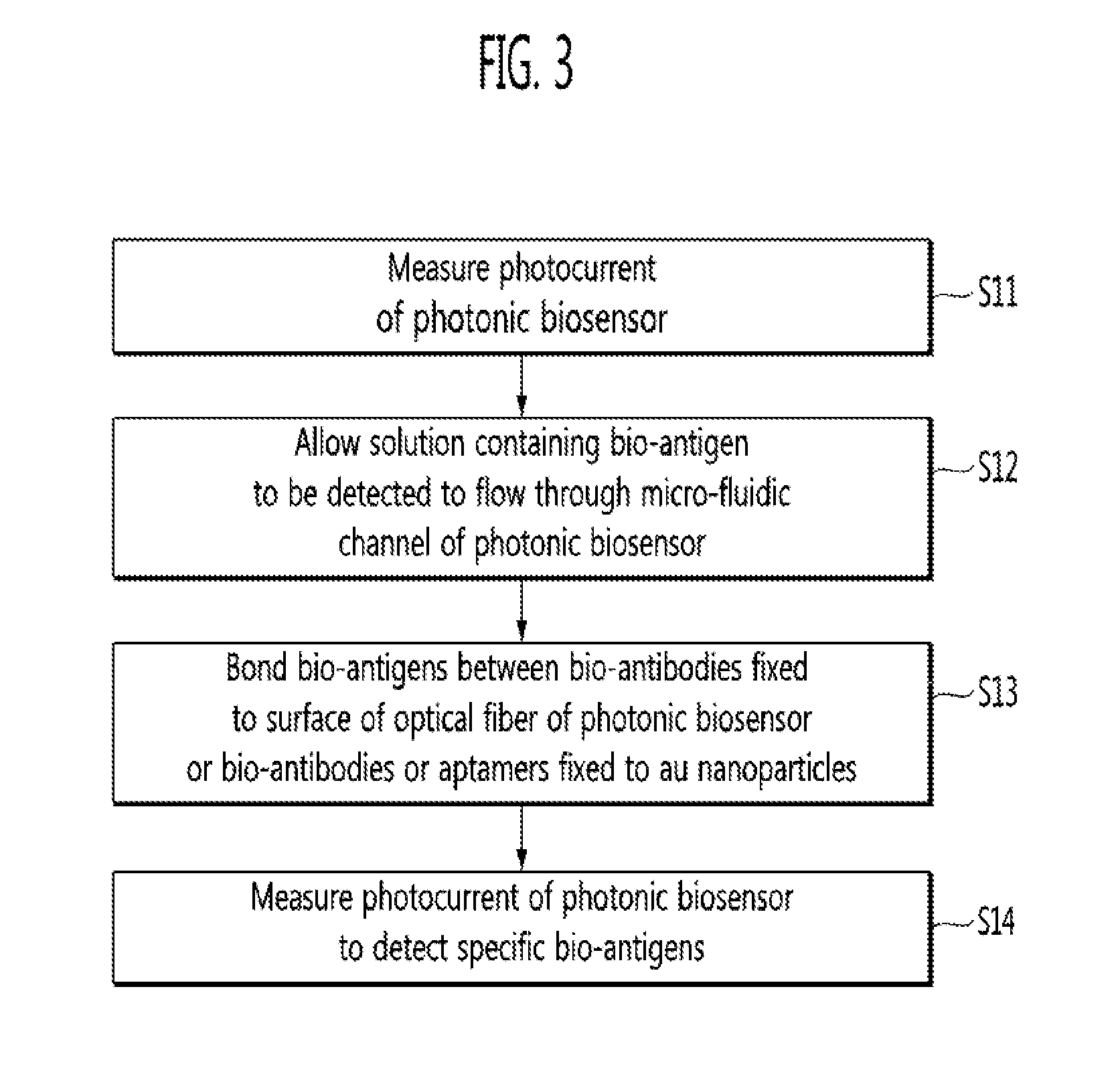
The present invention is a photonic biosensor that uses bio-antibodies or aptamers fixed to the surface of an optical fiber and Au nanoparticles to detect a bio-material. The biosensor measures a variation in photocurrent caused by the reaction between the bio-antibodies or aptamers and the bio-material. The biosensor includes a light emitting diode, a PD, an optical fiber, and a micro-fluidic channel with Au nanoparticles on which the bio-antibodies or aptamers are fixed. The biosensor can detect specific bio-antigens in a solution containing them. The technical effect of the invention is a highly sensitive and specific method for detecting bio-materials using a photonic biosensor.

Problems solved by technology

The above-described method involves an additional process of labeling a specific antibody with a fluorescent material expressing specific color, thus complicating the entire process and increasing the process cost.
Accordingly, a very complicated optical system may be required to configure the light source and the detector, thus increasing the fabrication cost of the biosensor.

Method used


Image

  • Photonic biosensor, photonic biosensor array, and method of detecting biomaterials using the same
  • Photonic biosensor, photonic biosensor array, and method of detecting biomaterials using the same
  • Photonic biosensor, photonic biosensor array, and method of detecting biomaterials using the same

Examples


Embodiment Construction

[0028]The present invention will now be described more fully hereinafter with reference to the accompanying drawings, in which exemplary embodiments of the invention are shown. Descriptions of well-known components and processing techniques are omitted so as not to unnecessarily obscure the embodiments of the present invention. Like numbers refer to like elements throughout.

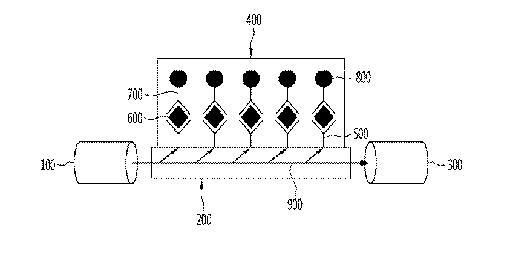
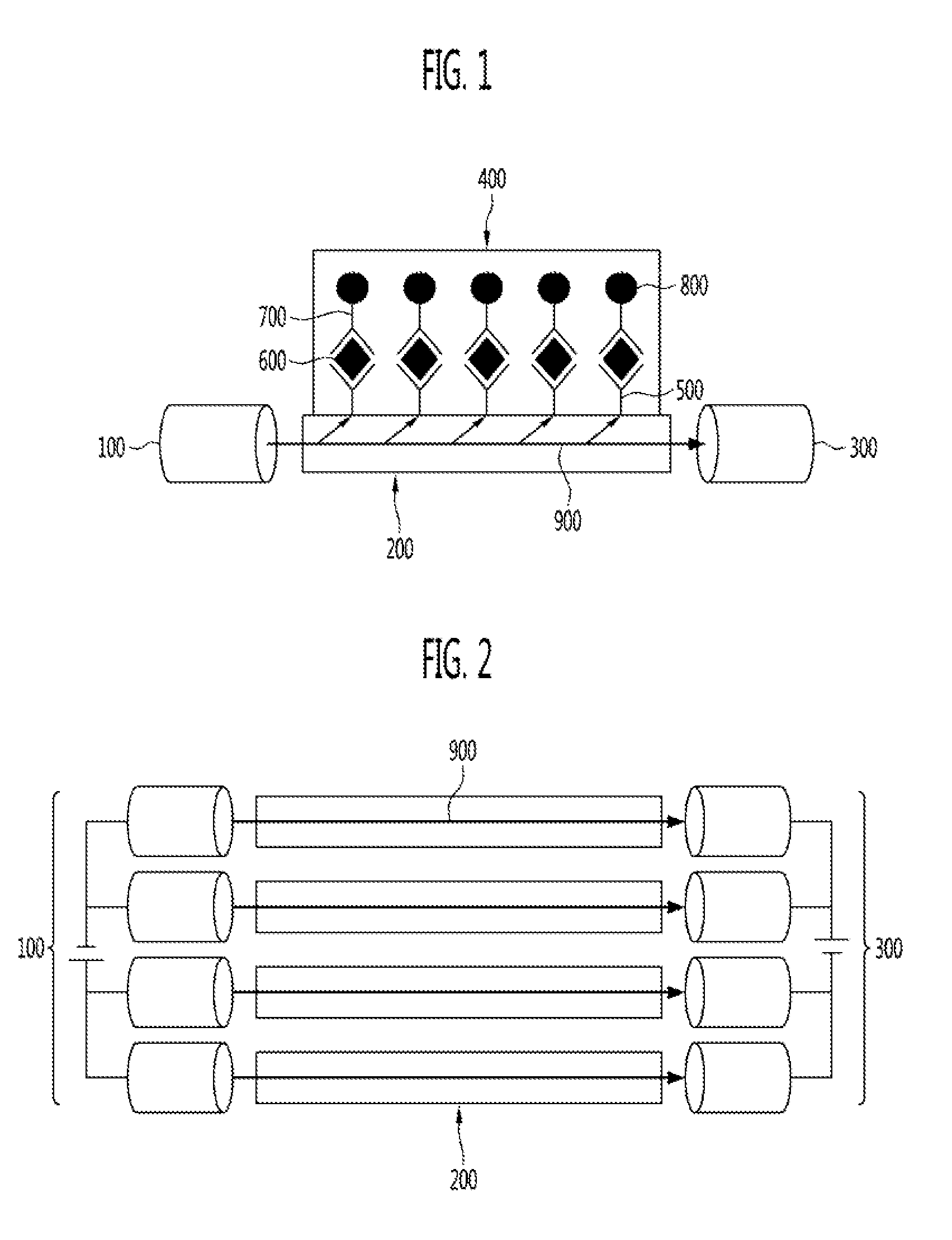
[0029]FIG. 1 is a schematic diagram of a structure of a photonic biosensor according to an exemplary embodiment of the present invention, and FIG. 2 is a schematic diagram of a photonic biosensor array including a plurality of photonic biosensors according to an exemplary embodiment of the present invention.

[0030]Referring to FIG. 1, a photonic biosensor according to an exemplary embodiment of the present invention may include a light emitting diode 100, a photodiode (PD) 300, an optical fiber 200 configured to connect the light emitting diode 100 with the PD 300, and a micro-fluidic channel 400 disposed on the o...


PUM

PropertyMeasurementUnit
lengthaaaaaaaaaa
lengthaaaaaaaaaa
physical adsorptionaaaaaaaaaa

Abstract

A photonic biosensor, a photonic biosensor array, and a method of detecting a bio-material using the same are provided. The photonic biosensor includes a light emitting diode configured to emit light, a photodiode (PD), an optical fiber configured to connect the light emitting diode with the PD, and a micro-fluidic channel disposed on the optical fiber. Bio-antibodies or aptamers are fixed to the surface of the optical fiber, and the micro-fluidic channel includes gold (Au) nanoparticles to which bio-antibodies or aptamers are fixed. The photonic biosensor may be configured using absorption of surface plasmons in Au nanoparticles with respect to light traveling through the surface of the optical fiber configured to connect the light emitting diode with the PD, thus simplifying the manufacture of the biosensor and reducing the manufacturing cost.

Description

CROSS-REFERENCE TO RELATED APPLICATION[0001]This application claims priority to and the benefit of Korean Patent Application No. 10-2009-0115976, filed Nov. 27, 2009, the disclosure of which is incorporated herein by reference in its entirety.BACKGROUND[0002]1. Field of the Invention[0003]The present invention relates to a photonic biosensor, a photonic biosensor array, and a method of detecting a biomaterial using the same, and more specifically, to a photonic biosensor, a photonic biosensor array, and a method of detecting biomaterials using the same, which employ absorption of surface plasmon in gold (Au) nanoparticles with respect to light traveling through the surface of an optical fiber.[0004]2. Discussion of Related Art[0005]A biosensor may include a bio-sensing material and a signal detector and may be capable of selectively detecting a material to be analyzed. The bio-sensing material may be an enzyme, an antibody, or deoxyribonucleic acid (DNA), which may selectively react...

Claims


Application Information

Patent Timeline
Patent Type & Authority Applications(United States)
IPC IPC(8): G01N33/53G01N33/543C12M1/34G01N30/96
CPCB01L3/5027B01L2300/0877G01N21/05G01N2021/0346G01N21/554G01N21/7703G01N33/54373G01N21/253C12N15/115C12Q1/6834G01N21/27G01N33/483G01N33/563C12N2310/16
Inventor HUH, CHULKIM, KYUNG HYUNKIM, BONG KYUKO, HYUN SUNGKIM, WAN JOONGHONG, JONG CHEOLSUNG, GUN YONGPARK, SEON HEE
Owner ELECTRONICS & TELECOMM RES INST
Learn More