
Band control system, load distribution device and band control device

Inactive Publication Date: 2011-06-02
HITACHI LTD
View PDF1 Cites 3 Cited by
  • Summary
  • Abstract
  • Description
  • Claims
  • Application Information

AI Technical Summary

Benefits of technology

[0084]As a result, it is possible to suppress the use of the heavy user occupying the network facilities, and realize the fair use of the network without imposing load on general users.

Problems solved by technology

Under such a condition, with the conventional method, the band control is only allowed in units of the band control devices, whereby if the user uses a plurality of band control mechanisms at the same time, there is a problem that the band control can not be made for each user with the plurality of band control devices integrated.
With the conventional method (Nikkei NETWORK, September 2003, Page 72), the fairness may often lack among the users classified as the heavy user.
With the conventional method (Nikkei Communication, Apr. 15, 2008, Pages 52 to 56), the fairness may also often lack if the traffic is distributed over the plurality of band control devices.

Method used


Image

  • Band control system, load distribution device and band control device
  • Band control system, load distribution device and band control device
  • Band control system, load distribution device and band control device

Examples


Embodiment Construction

[0091]An embodiment of the invention will be described below with reference to the drawings.

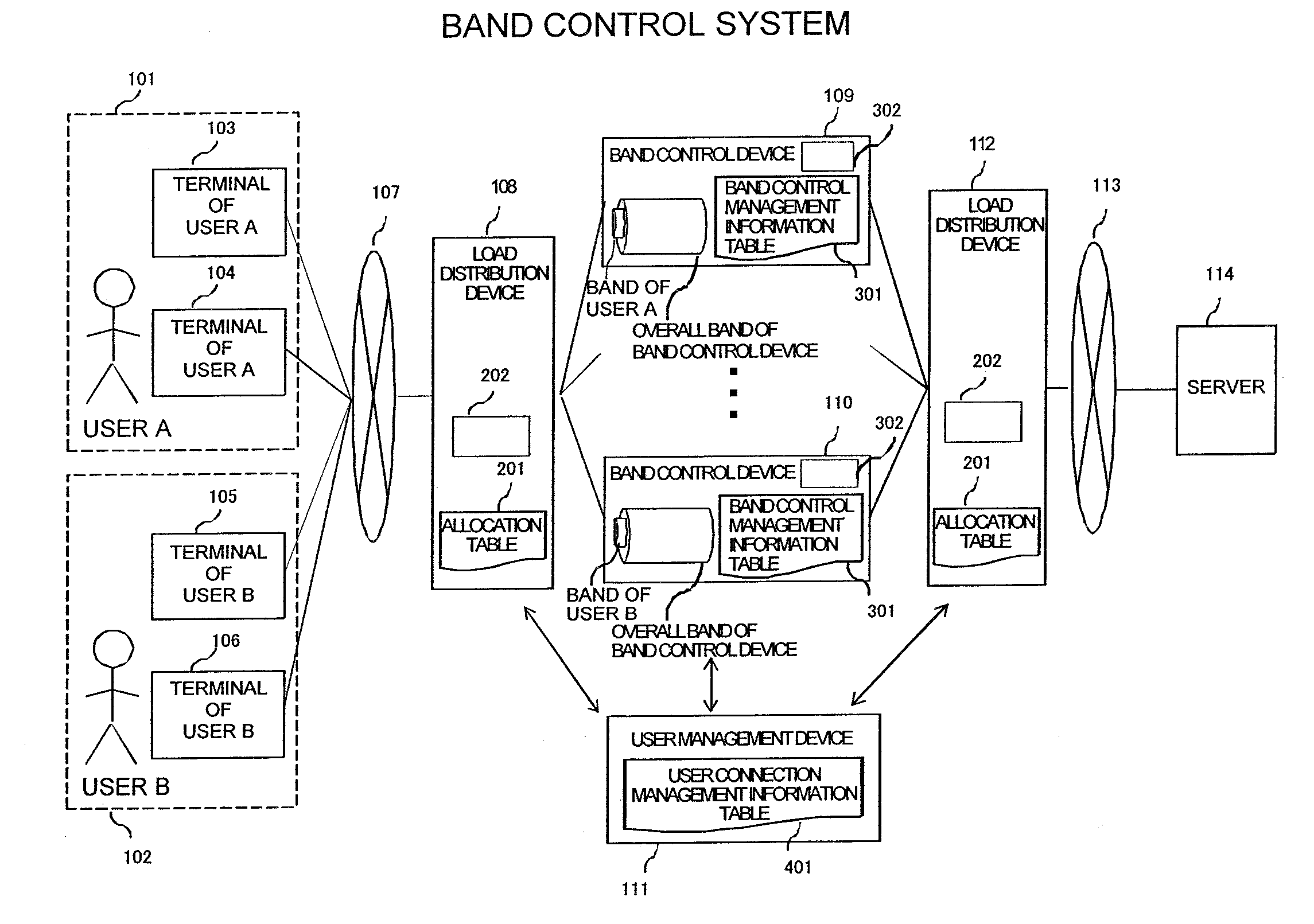
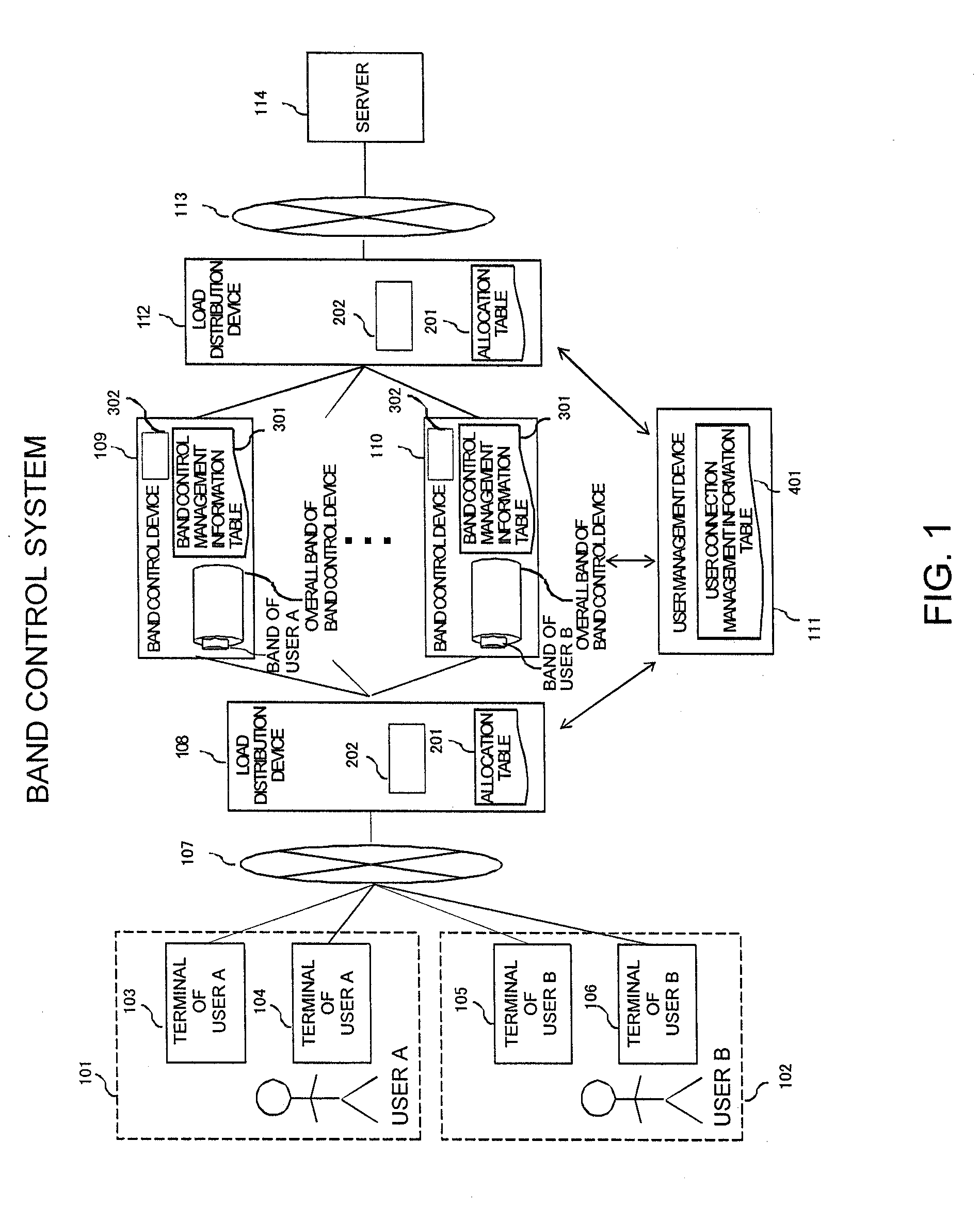
[0092]FIG. 1 is a diagram showing one configuration example of a band control system according to the embodiment of the invention.

[0093]In the example of FIG. 1, a user A 101 possesses a terminal 103 of a user A and a terminal 104 of the user A, and a user B 102 possesses a terminal 105 of a user B and a terminal 106 of the user B. Communication can be made from each terminal through a mobile communication network 107, a system according to this embodiment and an internet 113 to a server 114.

[0094]Also, the system according to this embodiment comprises a load distribution device 108, a load distribution device 112, a band control device 109, a band control device 110, and a user management device 111.

[0095]The load distribution device 108 comprises an allocation table 201 for uniquely managing the band control device that transfers traffic to a user identifier, and a load distribution process...


PUM


Abstract

Band control is conducted for each user by distributing traffic for each user in a case where a plurality of band control devices are required due to increased traffic and under the condition where the user uses a plurality of terminals or has a plurality of IP addresses with one terminal to generate a plurality of communications at the same time. The band control is performed for each user, using a load distribution device for specifying a user identifier such as a contractor number or telephone number from the source IP address used by the users in making the communication, and transferring the traffic based on the user identifier, a user management device for managing the correspondence between the user identifier and the source IP address, and a plurality of band control devices for managing the traffic for each user identifier, and making the band control of traffic for each user through a transparent process installed on the network path and not recognized by the originator and recipient of the communication.

Description

CLAIM OF PRIORITY[0001]The present application claims priority from Japanese patent application JP 2009-269818 filed on Nov. 27, 2009, the content of which is hereby incorporated by reference into this application.BACKGROUND OF THE INVENTION[0002]1. Field of the Invention[0003]The present invention relates to a band control system, a load distribution device and a band control device, and more particularly to a band control system, a load distribution device and a band control device in which traffic subject to an internet connection service with a mobile terminal or the like is controlled in distributed band for each user.[0004]2. Description of the Related Art[0005]In recent years, with the development and spread of an internet technique and a mobile communication technology, the amount of network traffic increases.[0006]As the number of users using the network increases, there occur differences in the use frequency of the users, and the traffic of partial heavy user with high use...

Claims


Application Information

Patent Timeline
IPC IPC(8): H04L12/26H04L12/28G06F13/00H04L47/20
CPCH04L47/125H04W72/0486H04W28/16H04L47/14H04W28/08H04W72/52H04W8/04
Inventor IIZAWA, RYOISHIKAWA, YUUDAIOGAWA, TAKAHIRO
Owner HITACHI LTD
Learn More