
Method for producing the rotor winding of an electrical machine, and an electrical machine with a rotor winding which is produced in accordance with this method

a technology of rotor winding and electrical machine, which is applied in the direction of synchronous machines with stationary armatures, synchronous machines, stator/rotor bodies, etc., can solve the problems of resilient expansion of the formed wire eyelet on the connection lug, and the danger of short circuits occurring to the winding wire eyelets of adjacent connection lugs, so as to reduce the torque ripple, improve the commutation, and reduce the inductance of the pole teeth

Active Publication Date: 2011-06-02
ROBERT BOSCH GMBH
View PDF12 Cites 10 Cited by
  • Summary
  • Abstract
  • Description
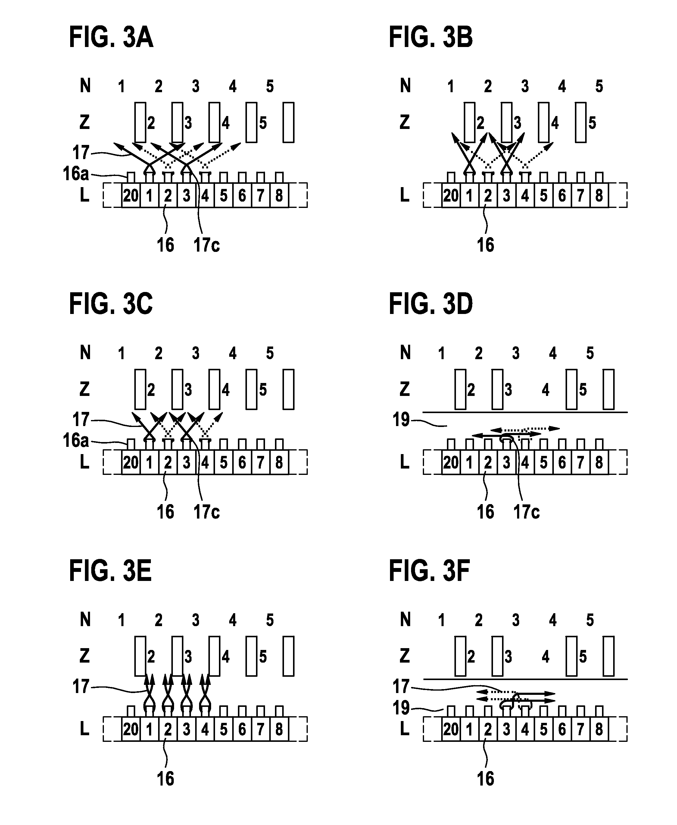
  • Claims
  • Application Information

AI Technical Summary

Benefits of technology

[0006]The method for producing the rotor winding of an electrical machine with the distinguishing features of claim 1 has the advantage of a resilient expansion of the eyelets of the winding wire on the connection lugs of the laminations being greatly reduced by at least one pole tooth being disposed between the winding wire being fed to and guided away from a connection lug and thereby ensuring a sufficient wrap of said connection lug. A further advantage is that in the case of these coils the winding wire cannot slide down between the coil and the connection lug to the commutator when the coils continue to be continuously wound. This results from the fact that at most two pole teeth are situated between the winding wire being fed and guided away from said connection lug, and consequently the winding wire does not extend over a large circumference.
[0009]An improved and uniform guidance of the winding wire on the commutator side of the rotor thus occurs as a result of the winding wire being led from the coil to the lamination, respectively from the lamination to the coil, in each case between two additional pole teeth situated closer to the lamination for at least a portion of coils, which are continuously wound in succession. Care should thereby be taken to ensure that two pole teeth lie between the respective lamination and the point where the winding wire is fed through. As an alternative thereto, it can be advantageous in armature embodiments, wherein sufficient room is available between the commutator and the pole teeth of the armature, if for preferably a first portion of the coils, which are continuously wound in succession, the winding wire is led from the coil to the lamination as well as from the lamination to the next coil across a supporting ring disposed on the rotor shaft. In so doing, the coils are offset to the lamination in each case by at least 90 E.
[0010]In order to reduce the torque ripple and improve the commutation, the inductance in the pole teeth is reduced in an efficient manner as a result of at least the coils, which are provided with an angular error in relation to the pole division, being wound so as to be distributed onto two pole teeth situated across from each other. In addition, the force components at the pole teeth situated opposite to each other, which are caused by supplying current to the coils, are thereby equally large and consequently in an advantageous manner cancel each other out. All coils are thereby expediently divided and are wound in each case onto two pole teeth situated opposite to each other. The rotor winding can thereby be particularly easily produced if the divided coils are in each case continuously wound in succession as coil halves connected in series. Provision is made alternatively thereto for the divided coils if necessary to be connected in each case as coil halves in parallel to their common initial and end lamination. It is advantageous in achieving a symmetric coil configuration for the coils with angular error and the coils without angular error to be continuously wound in succession in uniform sequence. In a modification to the invention, it can be advantageous for achieving a favorable torque ripple or a uniform distribution of weight across the rotor circumference if the coil halves are in each case wound with different numbers of windings at least for a portion of the coils divided up on pole teeth situated opposite each other

Problems solved by technology

In the exemplary embodiments depicted and described in this publication, a problem arises by the winding wire, which often in alternating succession contacts the coils to the commutator laminations, being on the one hand directly guided out of a slot to the connection lug of a lamination and on the other hand having to be guided out of the slot over a large circumferential area to the connection lug.
This has the disadvantage of enabling the thus formed wire eyelet on the connection lug to resiliently expand.
Because when contacting the winding wire on the connection lug the insulating varnish of said winding wire is melted in the region of the eyelet by so-called hot staking, the danger exists of short circuits occurring to the winding wire eyelets of adjacent connection lugs.

Method used


Image

  • Method for producing the rotor winding of an electrical machine, and an electrical machine with a rotor winding which is produced in accordance with this method
  • Method for producing the rotor winding of an electrical machine, and an electrical machine with a rotor winding which is produced in accordance with this method
  • Method for producing the rotor winding of an electrical machine, and an electrical machine with a rotor winding which is produced in accordance with this method

Examples


Embodiment Construction

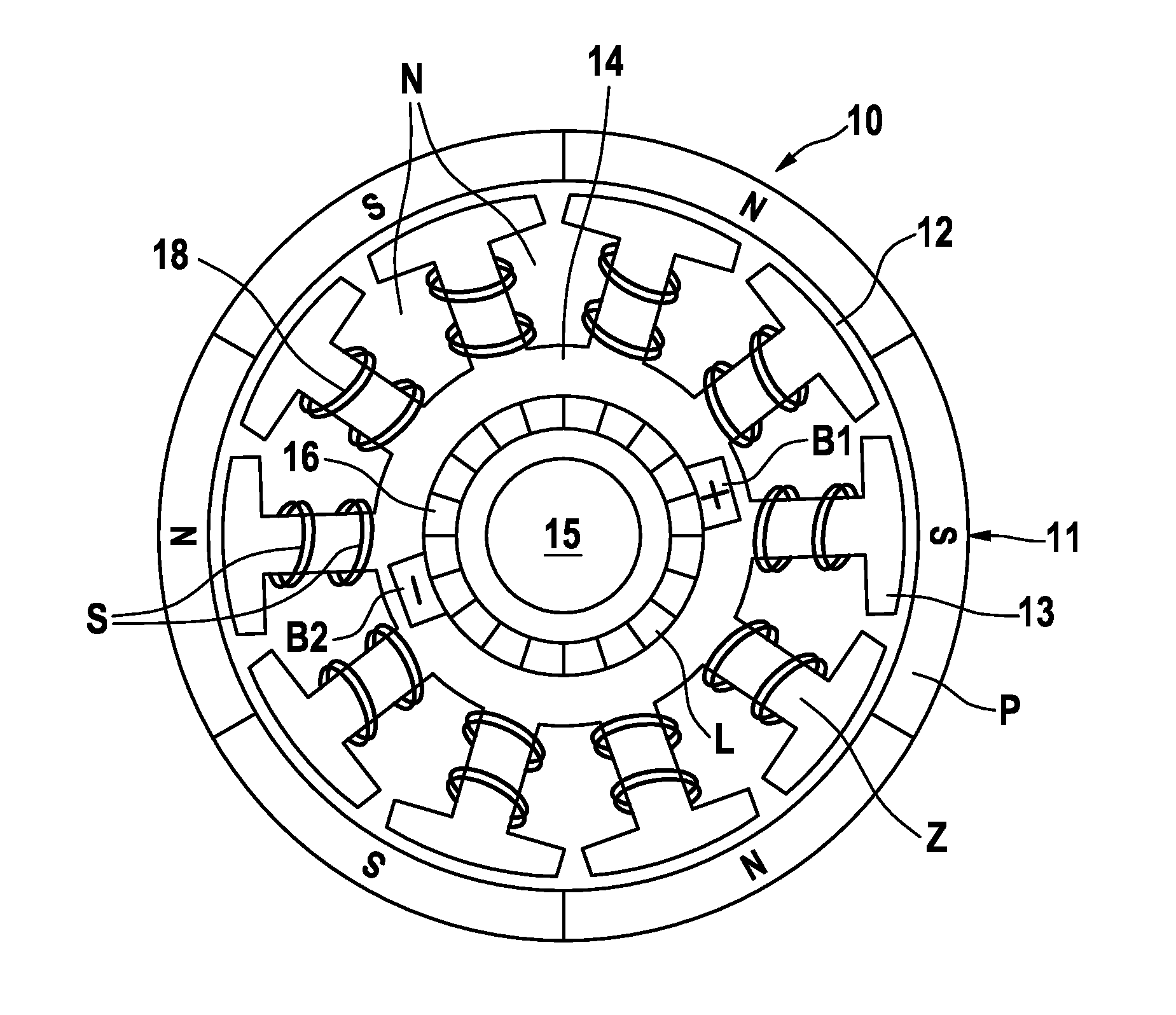
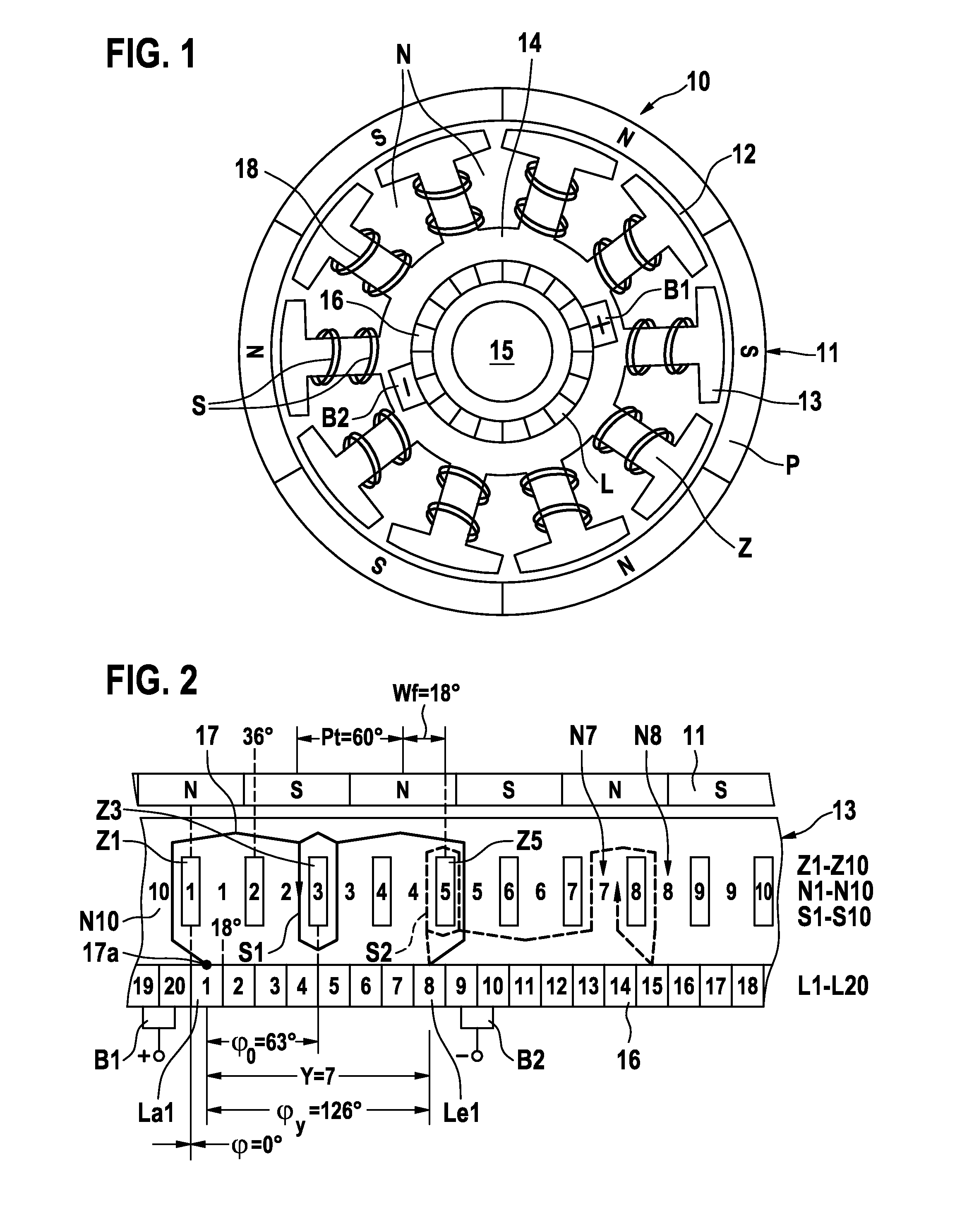
[0028]A permanent-magnetically excited six-pole direct current motor is schematically depicted in a front view in FIG. 1 as a first exemplary embodiment and is denoted with the numeral 10. Machines of this type are preferably used for actuating drives, radiator fans and the like in motor vehicles and have to reliably operate under heavy loads if possible for the entire service life of the motor vehicle. Their construction must therefore be as robust as possible. The electrical machine 10 has a six-pole stator 11, which interacts with a commutator rotor 13, subsequently referred to as rotor, via a working air gap 12. The rotor 13 consists of a lamination stack 14, which is attached to a rotor shaft 15 that is supported on both sides. Ten uniformly spaced pole teeth Z are disposed on the circumference of the lamination stack 14. Slots N for receiving in total twenty coils S of a rotor winding 18 are configured between said pole teeth Z. The coils S are thereby produced by automatic co...


PUM

PropertyMeasurementUnit
Circumferenceaaaaaaaaaa
Erroraaaaaaaaaa

Abstract

The invention relates to a method for producing the rotor winding of an electrical machine having at least four exciter poles in the stator (11) and having a commutator rotor (13) with a number of slots (N) and pole teeth (Z) which deviates from the number of exciter poles, and having a number of individual tooth coils (S) and laminations (L) which is at least twice as high as the number of pole teeth, wherein the individual tooth coils are wound, starting from the first coil (S1) onto in each case that pole tooth with the lowest angular error (Wf) in relation to a pole division (Pt). In order to permit non-critical guidance of the winding wire (17) in the region of the lamination connections, provision is made, at least in the case of a last-wound section (B) of the coils (S), preferably in the case of all of the coils, for the winding wire (17), with which contact is made by a lamination (L) in each case between two coils (S), to be fed from one side of the lamination (L) and guided away from the other side, and for at least one pole tooth (Z), but at most two pole teeth (Z) to be situated between the slot (N) from which the winding wire (17) of the lamination (L) is fed and the slot (N) at which said winding wire is guided away from the lamination (L).

Description

[0001]The invention relates to a method for producing the rotor winding of an electrical machine according to the class of claim 1 as well as to an electrical machine having a rotor winding produced in accordance with this method according to the class of claim 10.TECHNICAL FIELD[0002]It is known from the German patent publication DE 10 2004 062 813 A1 how to select the number of the slots and pole teeth, which alternate on the circumference of a commutator rotor, such that it deviates from the number of exciter poles in the stator. The number of the so-called individual tooth coils is equal to the number of commutator laminations but twice as high as the number of pole teeth and slots. The coils, which are wound on the pole teeth in an evenly distributed manner, are thereby contacted on the connection lugs of the laminations with a predefined lamination interstice length. Starting from the first coil, all further coils, which are continuously wound in succession, are wound onto in ...

Claims


Application Information

Patent Timeline
IPC IPC(8): H02K3/28H02K15/02
CPCH02K23/38H02K3/04H02K3/28Y10T29/49012H02K23/62H02K57/00Y10T29/49009H02K21/22H02K99/00
Inventor ROOS, GERALD
Owner ROBERT BOSCH GMBH
Learn More