
Fog-resistant structure and protective device for eyes

a technology of protective device and structure, which is applied in the direction of protective garment, goggles, instruments, etc., can solve the problems of large power consumption, inconvenience of wearing, and significant difference in temperature between the face surface of the wearer and the lens or shield, so as to reduce the amount of wasted power consumption, simplify the structure, and reduce the effect of was

Active Publication Date: 2011-06-02
SWANS
View PDF35 Cites 32 Cited by
  • Summary
  • Abstract
  • Description
  • Claims
  • Application Information

AI Technical Summary

Benefits of technology

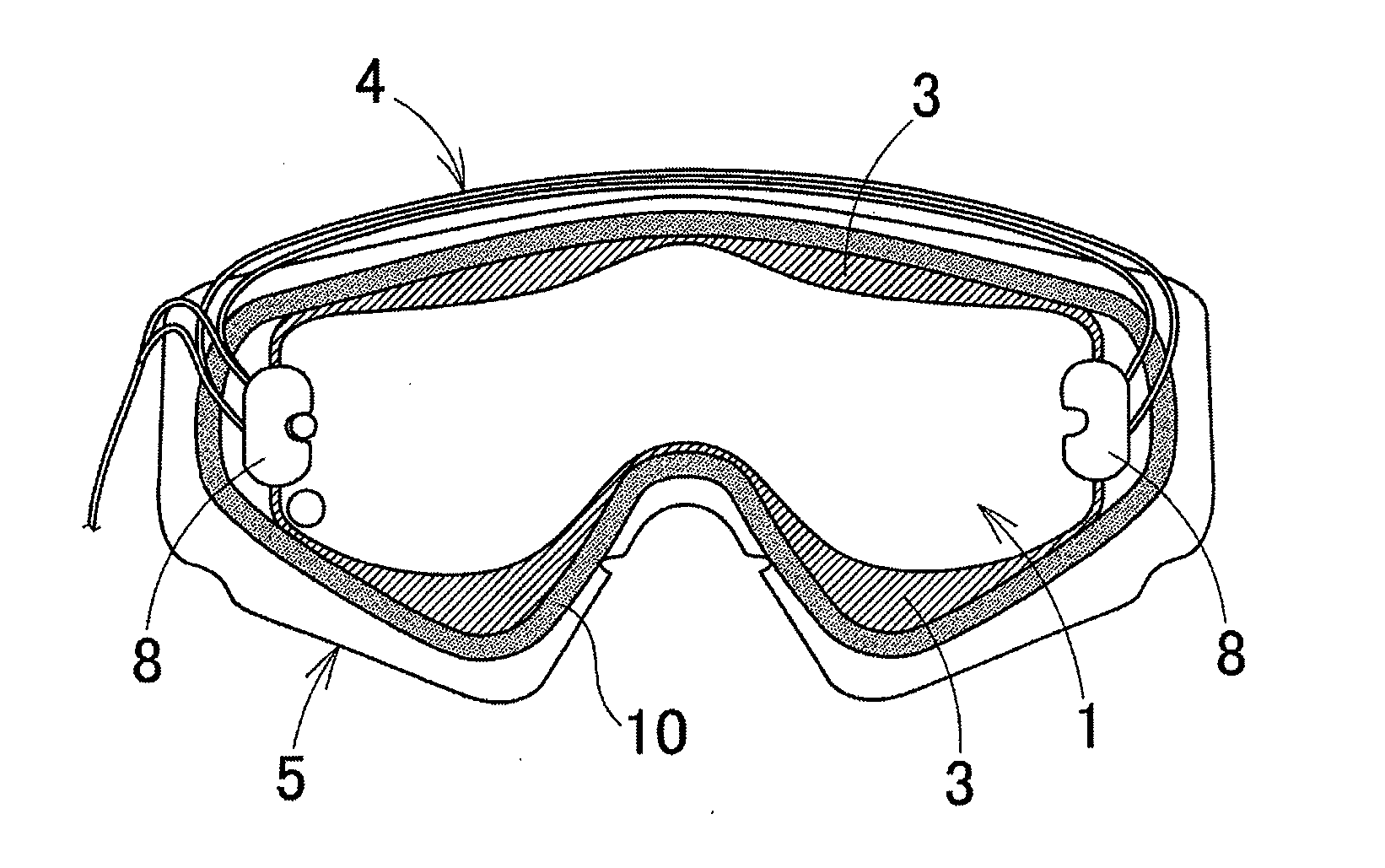
[0017]In view of this, the present invention has been made to solve the above conventional problems, and an object of the present invention is to provide a fog-resistant structure and a protective device for eyes in which each region of a lens or shield has no difference in temperature without regulating power supplied to a transparent conductive film, thereby eliminating wasted power consumption and allowing even a structure using a battery as a power supply to have much longer available time.
[0018]Further, another object of the present invention is to provide a fog-resistant structure and a protective device for eyes which have a simplified structure in which power supply lines are connected to linear electrodes to supply power to the transparent conductive film and which are difficult to fail and easy to maintain.
[0025]The present invention is configured as described above and thus each region of the lens or shield has no difference in temperature without regulating power supplied to the transparent conductive film, thereby eliminating wasted power consumption and allowing even a structure using a battery as the power supply to have much longer available time.
[0026]Further, the present invention has a simplified structure in which the power supply lines are connected to the linear electrodes and is difficult to fail and easy to maintain.

Problems solved by technology

However, when such a glass lens configuration is applied to the goggle lenses for skiing and motorcycling or shields for sports helmets, the external temperature contacting the outer surface of the lenses or shields is extremely lowered by the high speeds during skiing and motorcycling to cause a significant difference in temperature between the face surface of the wearer and the lenses or shields.
Therefore, a large power is needed to increase the temperature of the lenses or shields.
Thus, there is a problem with wasted power consumption and large-sized power supply causing inconvenience of wearing.
However, even for the goggle lenses for skiing and motorcycling or shields for sports helmets, the temperature in a central region of a lens or shield is relatively lowered and the temperature in opposite side regions of the lens or shield is relatively increased, thus causing a difference in temperature in those regions.
More specifically, in opposite side portions of the lenses or shields, the spacing between linear electrodes is small and thus the electrical resistance is low; current is easy to flow and thus the amount of heat generation increases relatively, while in a central region of a lens or shield, the spacing between linear electrodes is large and thus the electrical resistance is high; current is difficult to flow and thus the amount of heat generation decreases relatively.
However, when an electric current is applied to increase the temperature of the central region to a degree required to prevent fogging, an electric current higher than that thereof flows through the regions of opposite side portions, thereby causing wasted power consumption.
In particular, a structure using a battery as the power supply such as helmet shields has a problem in that the available time of the anti-fog heater is very limited.
Unfortunately, the helmet shield disclosed in Patent Literature 2 has a problem in that in order to regulate power supplied to the transparent conductive film 22, a constant-voltage circuit having a plurality of output voltages needs to be interposed between the vertically divided linear electrodes 23a to 23c and 24a to 24c and the power supply or a power regulating controller needs to be provided, thereby complicating the structure and increasing the unit price of the product.
Further, the helmet shield disclosed in Patent Literature 2 has a problem in that in order to supply power to the transparent conductive film 22, power supply lines 27a to 27d need to be connected to the vertically divided linear electrodes 23a to 23c and 24a to 24c respectively, thereby complicating the wiring of the plurality of power supply lines 27a to 27d and causing an easy-to-fail and hard-to-maintain problem.

Method used


Image

  • Fog-resistant structure and protective device for eyes
  • Fog-resistant structure and protective device for eyes
  • Fog-resistant structure and protective device for eyes

Examples


example 1

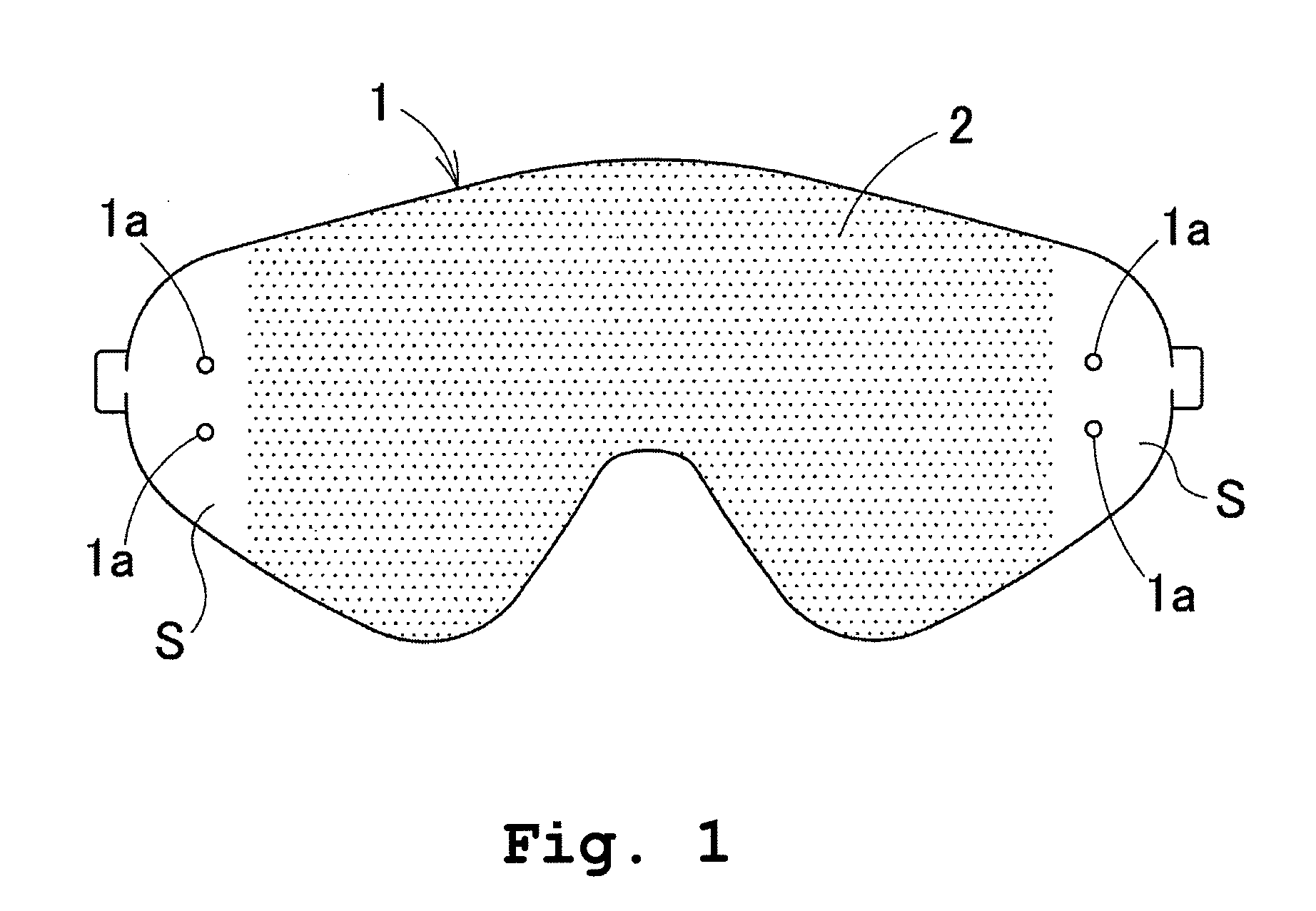
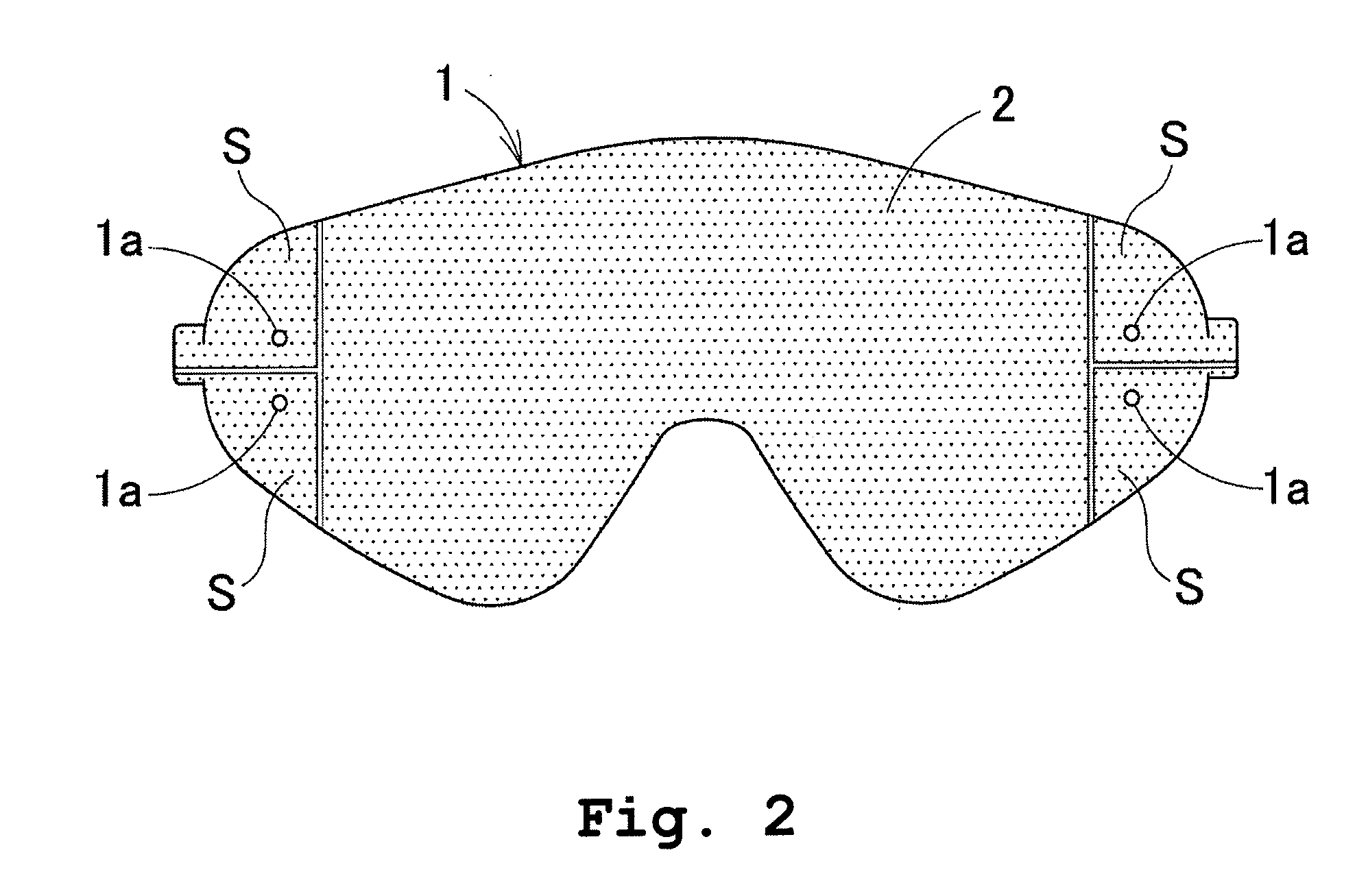
[0051]A polycarbonate resin sheet (a thickness of 1 mm) whose surface was covered with anti-fog coating was punched out into a goggle-like lens shape. Masking was made on the reverse side of the lens covered with anti-fog coating, so as to extend within 20 mm from each of the opposite ends of the lens. Then, ITO sputtering was performed to form an ITO transparent conductive film with a film thickness of 190 nm and a surface resistance of 30 Ω / cm2.

[0052]Then, a linear conductive paste made of silver paste was disposed on the ITO transparent conductive film by silk printing. One of the two line shapes was a shape of a line along the inner circumference of the upper half of the outer circumference of the goggle lens with a line width varying from 1 to 5 mm; and the other one was a shape of a line along the inner circumference of the lower half thereof with a line width varying from 1 to 15 mm. The transparent conductive film portion interposed between the two lines formed a transparent...


PUM


Abstract

A fog-resistant structure and a protective device for eyes is configured such that a transparent conductive film is formed on one surface of a lens or shield, a linear electrode is provided on upper and lower portions of the surface of the lens or shield so that each of a central region and opposite side regions of the lens or shield has substantially equal spacing between the upper and lower linear electrodes. Thus each region of the lens or shield has no difference in temperature without regulating power supplied to the transparent conductive film, thereby eliminating wasted power consumption and allowing even a structure using a battery as the power supply to have much longer available time.

Description

CROSS REFERENCE TO RELATED APPLICATIONS[0001]This application claims priority of Japanese application No. 2009-274968 filed on Dec. 2, 2009, the entire contents of which is hereby incorporated herein by reference.BACKGROUND OF THE INVENTION[0002]1. Field of the Invention[0003]The present invention relates to a fog-resistant structure such as lenses for nearsighted glasses, farsighted glasses, and sunglasses; lenses for goggles for skiing and goggles for motorcycling; and shields for eye protection such as sports helmets and hard hats; and a protective device for eyes including the fog-resistant structure such as glasses, sunglasses, goggles, and helmet shield devices.[0004]2. Description of the Related Art[0005]Glass lenses and like fog in such a manner that heat generated from the face surface of the wearer causes a difference in temperature between the air contacting the lens inner surface facing the face surface and the external air contacting the lens outer surface, and water va...

Claims


Application Information

Patent Timeline
IPC IPC(8): A61F9/02
CPCG02C11/08A61F9/028A42B3/245A61F9/02A61F9/04H05B3/84
Inventor MATSUMOTO, KIMIOYAMAGUCHI, JINDAIYOSHIKAWA, KEISHI
Owner SWANS
Learn More