


Quick Research
Generate reliable direction feasibility study reports for your R&D in just a few steps.

Technical Q&A
Discover and master advanced knowledge NOW. Basics, ideas, possibilities, all at once.

Find Solutions
As an expert in R&D theories, this can generate solutions to your technical problems instantly.

Evaluate Feasibility
Analyze your overall solution with one click, know your potential R&D risks in advance.

Monitor Landscape
Get weekly tech updates, stay abreast of the latest tech innovations and key insights.
Methods and devices for treating heart failure
a heart failure and heart disease technology, applied in the field of heart failure treatment methods and devices, can solve the problems of congestive heart failure, inability to adequately pump blood throughout the body, and hundreds of thousands of deaths in millions of people, and achieve the effect of preventing the collapse of the graft wall
- Summary
- Abstract
- Description
- Claims
- Application Information
AI Technical Summary
Benefits of technology
Problems solved by technology
Method used
Image

Examples
embodiment 1
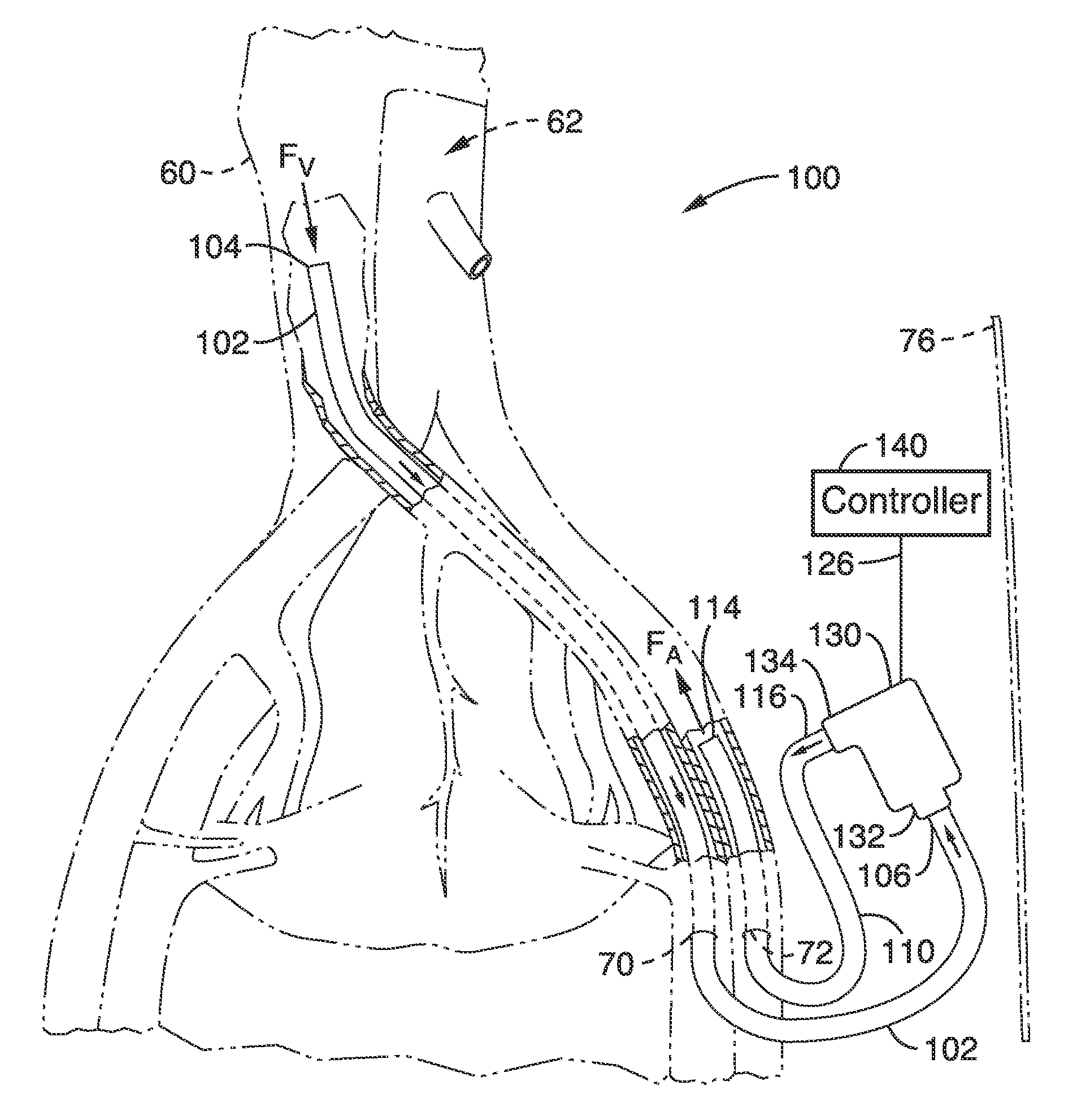
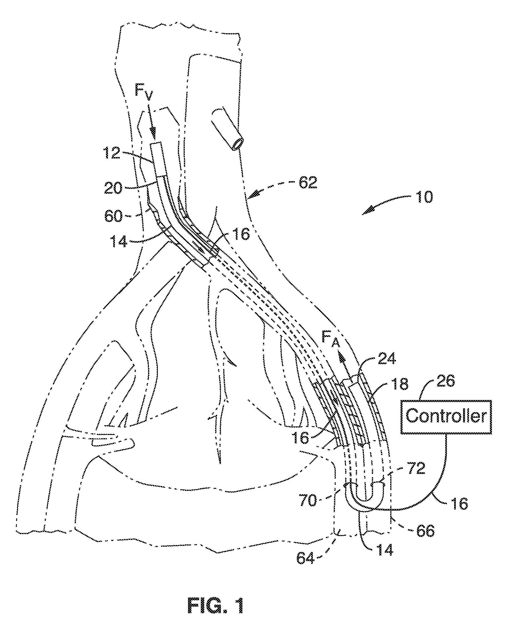
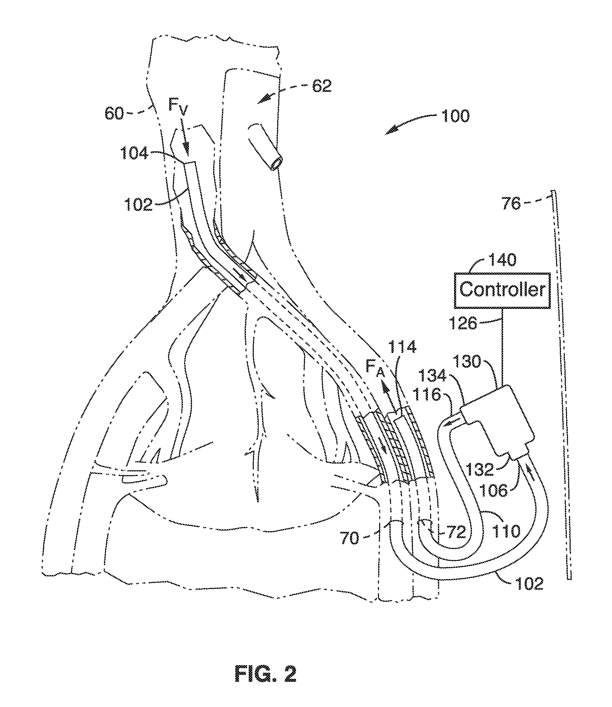
[0081]2. An apparatus as recited in wherein the first access location comprises a location along the femoral vein of the patient; wherein the second access location comprises a location along the femoral artery of the patient; and wherein the intake location comprises a location within the vena cava of the patient.
[0082]3. An apparatus as recited in embodiment 1, further comprising: a controller; a lead coupling the controller to the pump; wherein the controller is configured to power the pump from a location outside the venous circulatory system.
embodiment 3
[0083]4. An apparatus as recited in
[0084]wherein the cannula comprises a central channel for diverting blood flow and a secondary channels for housing the lead at least along a portion of the cannula.
[0085]5. An apparatus as recited in embodiment 3: wherein the cannula is collapsible to form a collapsed configuration for delivery to the first or second location, and is expandable to form an expanded configuration.
[0086]6. An apparatus as recited in embodiment 3: wherein the cannula comprises a reinforced mesh to retain the cannula in the expanded configuration once expanded.
embodiment 2
[0087]7. An apparatus as recited in wherein the cannula is coupled to one or more of the femoral vein or femoral artery via an anastomosed graft.
[0088]8. An apparatus as recited in embodiment 3: wherein the pump comprises a variable speed pump; wherein the controller comprises a processor for controlling said variable speed pump; wherein the controller is configured to control the speed of the pump to vary flow rate of venous blood into the systemic arterial circulation.
PUM
 Abstract
Description
Claims
Application Information
 - R&D Engineer
- R&D Manager
- IP Professional
- Industry Leading Data Capabilities
- Powerful AI technology
- Patent DNA Extraction
Browse by: Latest US Patents, China's latest patents, Technical Efficacy Thesaurus, Application Domain, Technology Topic, Popular Technical Reports.
© 2024 PatSnap. All rights reserved.Legal|Privacy policy|Modern Slavery Act Transparency Statement|Sitemap|About US| Contact US: help@patsnap.com