
Test Body, Test Arrangement, Method For Manufacturing Of A Test Body, And Method For Determining A Moisture Content Of The Insulation Of A Power Transformer During Drying Thereof

a technology for testing bodies and power transformers, which is applied in the direction of resistance/reactance/impedence, instruments, and weighing by absorbing components, etc., can solve the problems of inability to provide reliable measurement and above-hand approach, and achieve accurate and precise measurement, shorten the production time of the power transformer, and reduce the effect of drying tim

Inactive Publication Date: 2011-05-19
ABB TECH AG
View PDF28 Cites 8 Cited by
  • Summary
  • Abstract
  • Description
  • Claims
  • Application Information

AI Technical Summary

Benefits of technology

"The invention provides a test body, a test arrangement, and a method for accurately and precisely determining the moisture content in the laminated insulation of a power transformer during the drying process. This helps to optimize the drying process and shorten the production time of the power transformer. The test body has the same material as the laminated insulation and embedded electrodes, which are formed on one or more surfaces of plates or sheets made of the same material. The shape and size of the laminated structure are selected to resemble the moisture content characteristics of the laminated insulation of the power transformer. The invention also provides a method for manufacturing the test body and a method for determining moisture content in the laminated insulation of a power transformer during or after drying thereof. The technical effects of the invention include improved accuracy and precision in measuring moisture content, optimized drying process, and faster production time of power transformers."

Problems solved by technology

It has been noted that the above approach does not work properly.
In particular, the measurement does not provide reliable results.

Method used


Image

  • Test Body, Test Arrangement, Method For Manufacturing Of A Test Body, And Method For Determining A Moisture Content Of The Insulation Of A Power Transformer During Drying Thereof
  • Test Body, Test Arrangement, Method For Manufacturing Of A Test Body, And Method For Determining A Moisture Content Of The Insulation Of A Power Transformer During Drying Thereof
  • Test Body, Test Arrangement, Method For Manufacturing Of A Test Body, And Method For Determining A Moisture Content Of The Insulation Of A Power Transformer During Drying Thereof

Examples


Embodiment Construction

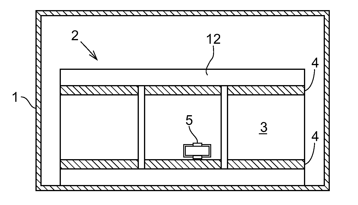
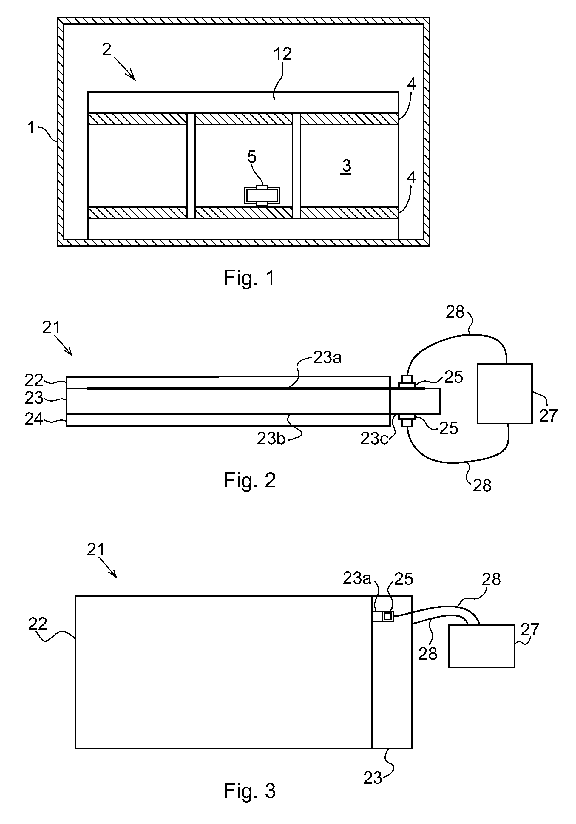
[0027]FIG. 1 shows a tank 1 in which the active part 2 of a power transformer is located in a drying step during the production of a power transformer. The active part 2 of the power transformer comprises paper-insulated copper conductors, pressboard details, etc. schematically indicated by reference numeral 3, and bottom and top insulation parts 4, each being comprised of a laminate structure of compressed cellulose plates, so-called cellulose pressboard. Further, a transformer core or transformer core sheet 12 is also shown as part of the active part 2 of the transformer.

[0028]During the drying step, vacuum is generated in the tank or container 1, while, simultaneously, the power transformer is subjected to a vapor phase heating, in order to lower the humidity of the electric insulation. Normally, the insulation material will have adopted a humidity of approximately 5-8 percent upon previously being exposed to free air during the production of the power transformer.

[0029]The dryin...


PUM

PropertyMeasurementUnit
humidityaaaaaaaaaa
humidityaaaaaaaaaa
dielectric frequencyaaaaaaaaaa

Abstract

A test body for use in determining moisture content in a laminated insulation of a power transformer by measuring a dielectric frequency response of the test body. The test body has a laminated structure of the same material as the laminated insulation, and has a shape and a size to obtain moisture content characteristics that resembles the moisture content characteristics of the laminated power transformer insulation. The test body further includes electrodes, which are embedded in the laminated structure.

Description

CROSS-REFERENCE TO RELATED APPLICATIONS[0001]The present application is a continuation of pending International patent application PCT / EP2009 / 057407 filed on Jun. 16, 2009 which designates the United States and claims priority from European patent application EP 08159112.5 filed on Jun. 26, 2008, the content of which is incorporated herein by reference.FIELD OF THE INVENTION[0002]The present invention relates to a test body for use in determining a moisture content in a laminated insulation of a power transformer. Further, the invention relates to a test arrangement including the above test body and to a method for manufacturing the test body.[0003]Yet further, the invention relates to a method for determining a moisture content in a laminated insulation of a power transformer during or after drying thereof. Preferably, the determination of moisture content is based on a measurement of dielectric frequency response, that is, a measurement of frequency dependence of capacitance or pe...

Claims


Application Information

Patent Timeline
Patent Type & Authority Applications(United States)
IPC IPC(8): G01R27/08H05K13/00
CPCY10T29/49002G01N27/223
Inventor ERIKSSON, THOMASGAFVERT, UNO
Owner ABB TECH AG
Learn More