Single continuous piece prosthetic tubular aortic conduit and method for manufacturing the same

Active Publication Date: 2011-05-12
MAQUET CARDIOVASCULAR LLC
View PDF2 Cites 22 Cited by
  • Summary
  • Abstract
  • Description
  • Claims
  • Application Information

AI Technical Summary

Benefits of technology

[0013]It is therefore one of the objects of the invention to provide a prosthetic aortic conduit which overcomes the drawbacks mentioned above and which upon implantation has the ability to expand radially outwardly whilst maintaining a degree of flexibility in the longitudinal direction.
[0019]It is further preferred that the conduit is provided with a third tubular portion which is part of the continuous conduit provided with resilient means which allows expansion of said third portion in a longitudinal direction.

Problems solved by technology

However, the lack of sinuses in a straight tube graft was found to negatively influence proper valve function, with the consequent risk of decreasing valve longevity (Kunzelman K. S., Grande K. J., David T. E., Cochran R. P., Verrier E. D.: Aortic root and valve relationships.
Thus in the Tirone David Type I technique for valve sparing operations, the use of a straight tube without a sinus component raises several problems: opening and closing of the native valve is not optimal.
For example, upon valve opening, the leaflets might impact on the graft and be potentially damaged.
The absence or delay in eddy current formation might alter valve closure causing some regurgitation.
Furthermore, the diastolic stress is borne only by the leaflet and is not shared with the sinuses causing a potential decrease in leaflet longevity.
However no method to produce such a conduit for use in aortic surgery is described in the patent.

Method used


Image

  • Single continuous piece prosthetic tubular aortic conduit and method for manufacturing the same
  • Single continuous piece prosthetic tubular aortic conduit and method for manufacturing the same
  • Single continuous piece prosthetic tubular aortic conduit and method for manufacturing the same

Examples


Embodiment Construction

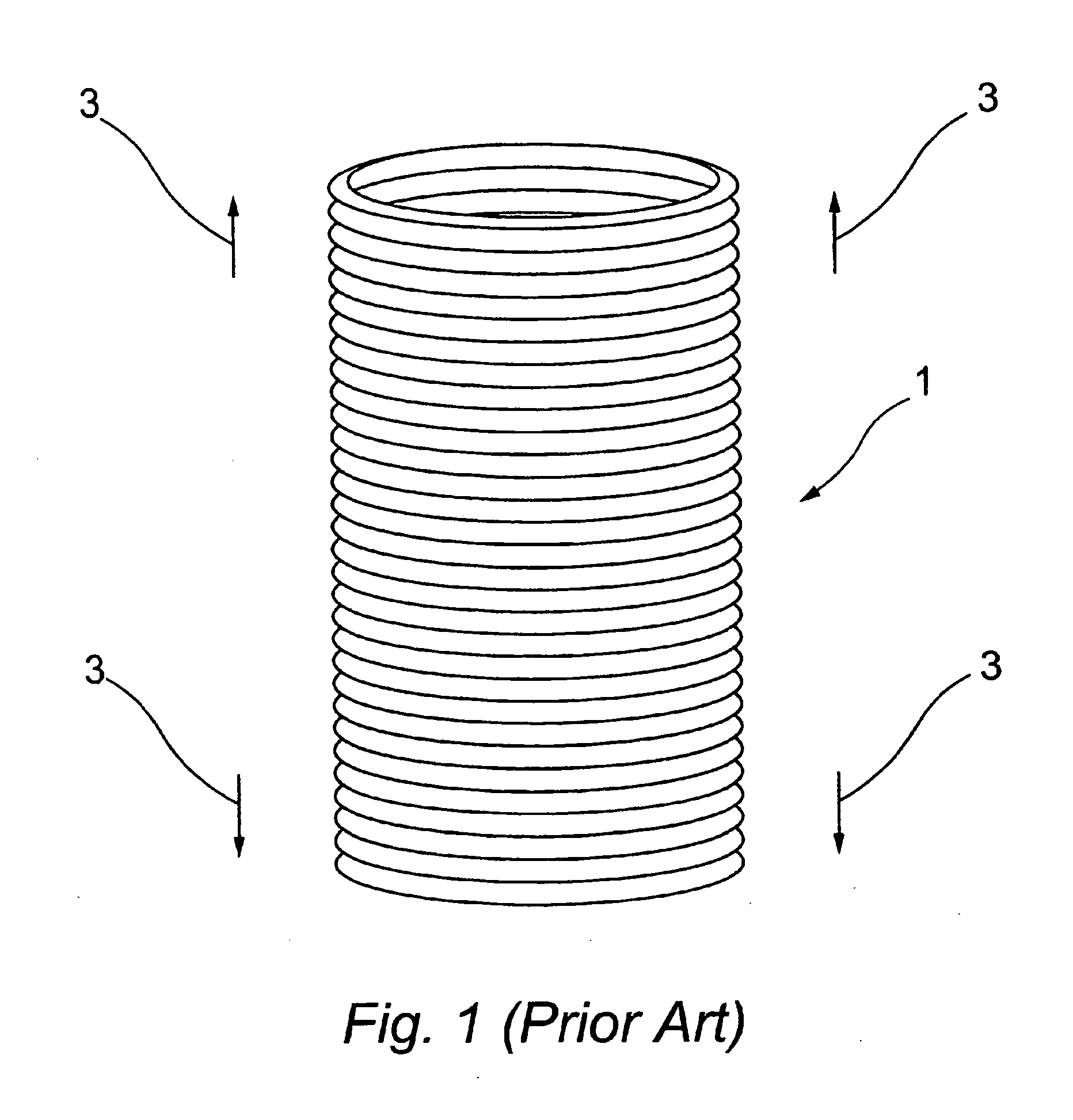
[0026]FIG. 1 shows a standard aortic conduit 1 of the type currently used in aortic surgery. This conduit is made of DACRON but any suitable biocompatible material such as polytetrafluoroethylene (PTFE) could be used. This standard aortic conduit 1 includes circumferentially extending pleats so that the corrugations lie perpendicular to the longitudinal axis of the prosthesis. These corrugations provide a degree of expansion in the longitudinal direction (indicated by the black arrows 3 in FIG. 1) and the conduit 1 can therefore significantly increase its length.

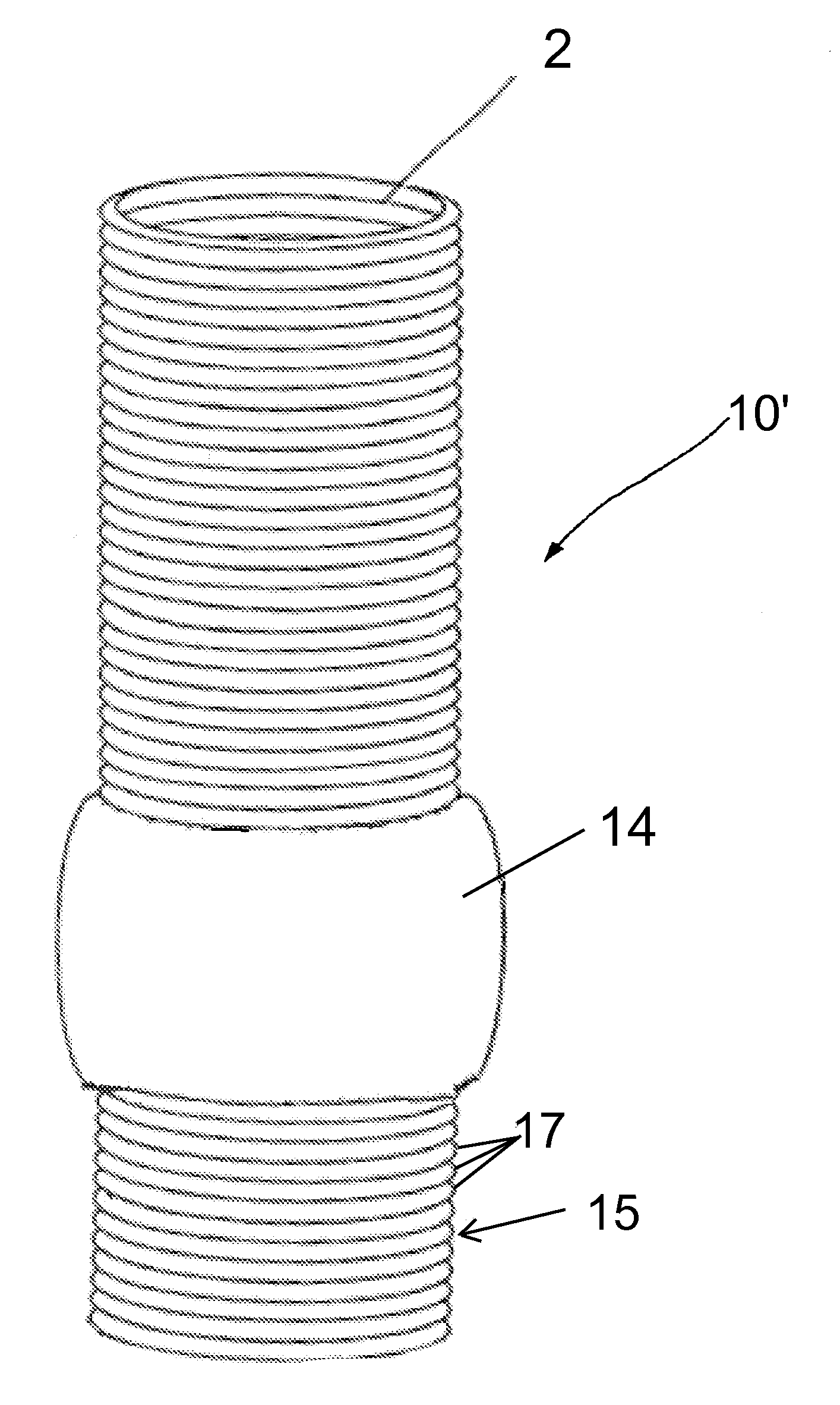
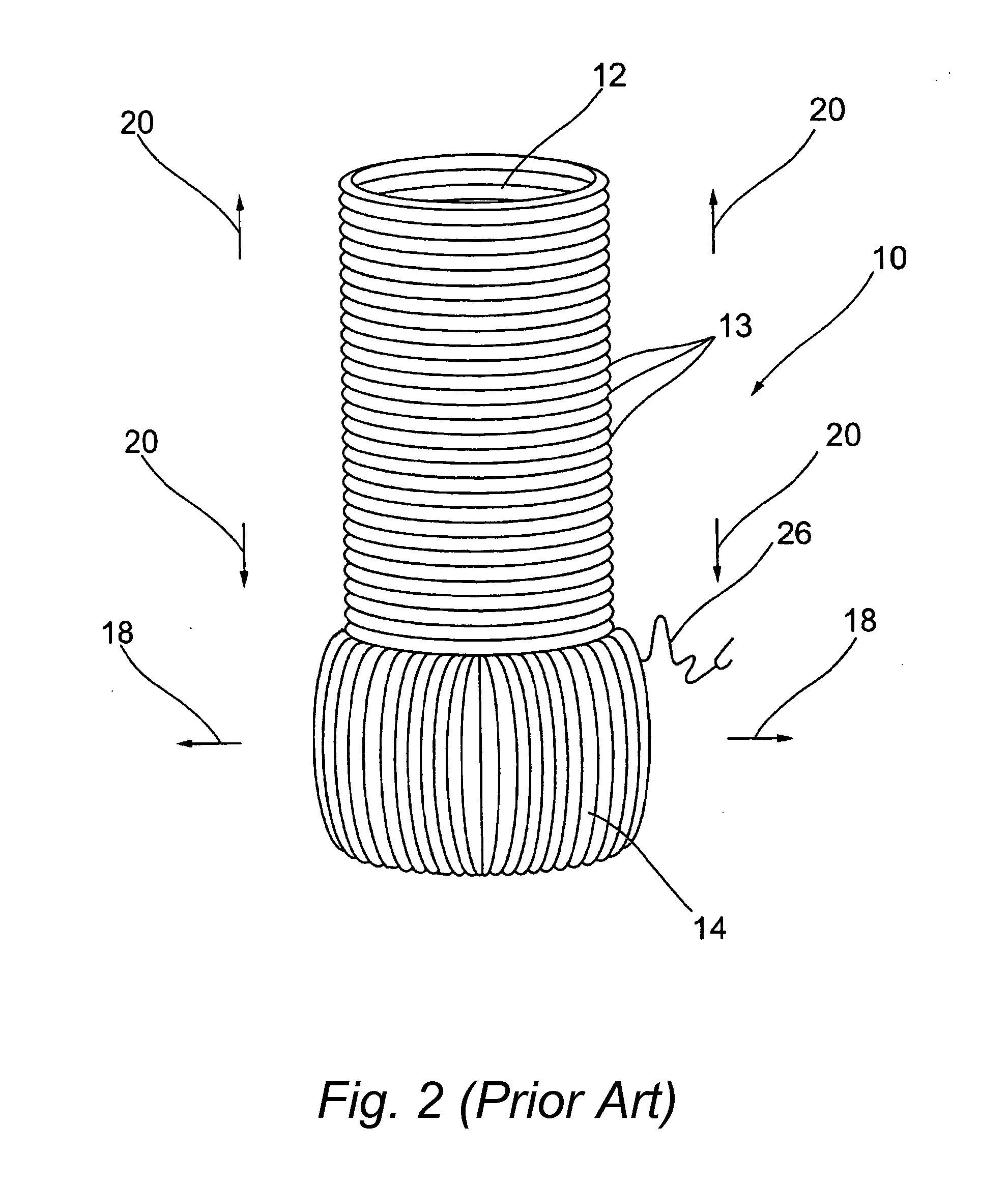
[0027]FIG. 2 shows a preferred embodiment of the conduit of the invention. The conduit 10 comprises two distinct tubular portions having a common axis. The first upper portion 12 is made from a standard aortic conduit similar to the one shown in FIG. 1 and is provided with circumferentially extending corrugations 13 successively provided along the axis of the tubular first portion 12. The second lower portion, or skirt porti...


PUM

PropertyMeasurementUnit
Diameteraaaaaaaaaa
Resilienceaaaaaaaaaa

Abstract

A prosthetic aortic conduit for replacing a root portion of an aorta is provided. The conduit comprises a continuous tubular conduit along a substantially common axis. A portion of the tubular conduit does not substantially deform in a longitudinal direction and has resilient means which allow said another portion of the conduit to be expandable in a lateral direction. The portion that is able to deform laterally mimics the function of the sinuses of Valsalva. The method of manufacturing such a conduit comprises the steps of having a continuous weave of rows of yarn or the equivalent with a change in tightness of the rows so that in some portion of the conduit it is expandable in the lateral direction and in some portion of the conduit it is expandable in the longitudinal direction.

Description

RELATED APPLICATIONS[0001]The present application is a continuation of U.S. application Ser. No. 12 / 387,201 filed Apr. 29, 2009, abandoned, which is a continuation of U.S. application Ser. No. 12 / 590,906 filed Nov. 16, 2009, abandoned, which is a continuation of U.S. application Ser. No. 11 / 655,438 filed Jan. 19, 2007, abandoned.BACKGROUND OF THE INVENTION[0002]The normal internal human aortic root conduit is provided with a sinus portion which has three sinuses (bulges) which surround the aortic valve. These sinuses are called sinuses of Valsalva and are arranged so that the cross-section of the sinus portion has a generally trefoil shape. The diameter and orifice area of the root are greater at the level of the sinus, decrease slightly at the base, but significantly decrease (by 20%) at the level of the sinotubular junction (where the sinus portion connects to the ascending portion of the aorta which supports the two iliac arteries).[0003]The sinotubular junction or sinus ridge an...

Claims


Application Information

Patent Timeline
IPC IPC(8): A61F2/06D03D3/02D03D41/00
CPCA61F2/06A61F2/2412A61F2/2475D03D1/02D10B2509/06D03D3/06D03D15/00D10B2321/042D10B2331/04D03D3/02D03D15/283
Inventor DU, GEORGE
Owner MAQUET CARDIOVASCULAR LLC
Why Eureka
Try Eureka