
Radio base station device, radio relay station device, and radio terminal device

a radio terminal and base station technology, applied in the field of wireless communication systems, can solve the problems of rrc connection failure and increase the latency before a connection is established, and achieve the effect of increasing frequency and deteriorating latency upon connection establishmen

Inactive Publication Date: 2011-05-12
SOVEREIGN PEAK VENTURES LLC
View PDF5 Cites 70 Cited by
  • Summary
  • Abstract
  • Description
  • Claims
  • Application Information

AI Technical Summary

Benefits of technology

[0002]The present invention relates to a wireless communication system comprising a radio base station device (eNodeB), a radio relay station device (Relay Node: also referred to as a Relay Station, a Repeater, and the like), and a radio terminal device (UE). More particularly, the present invention relates to a wireless communication system capable of reducing latency when establishing a communication connection and reducing the period of time until a radio terminal device starts communication.

Problems solved by technology

For example, there may be cases where an RRC connection setup signal message cannot be received and an RRC connection failure occurs despite transmitting a RACH preamble signal for a maximum number of transmissions or retransmitting an RRC connection request signal for a maximum number of retransmissions.
Such a delay may significantly increase the latency before a connection is established.

Method used


Image

  • Radio base station device, radio relay station device, and radio terminal device
  • Radio base station device, radio relay station device, and radio terminal device
  • Radio base station device, radio relay station device, and radio terminal device

Examples


first embodiment

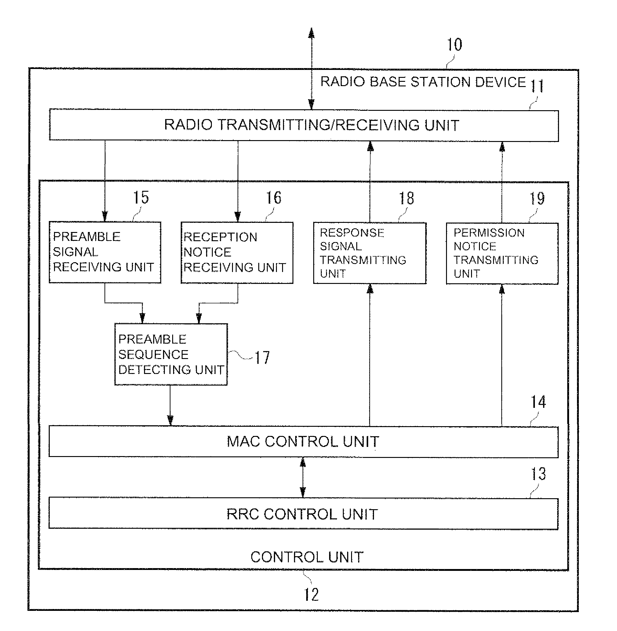
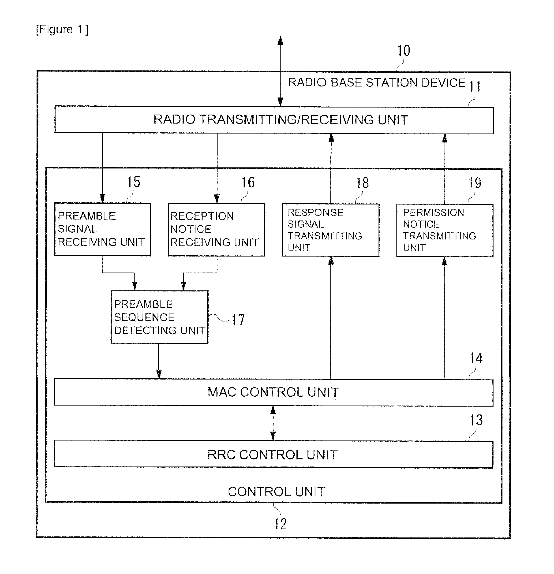
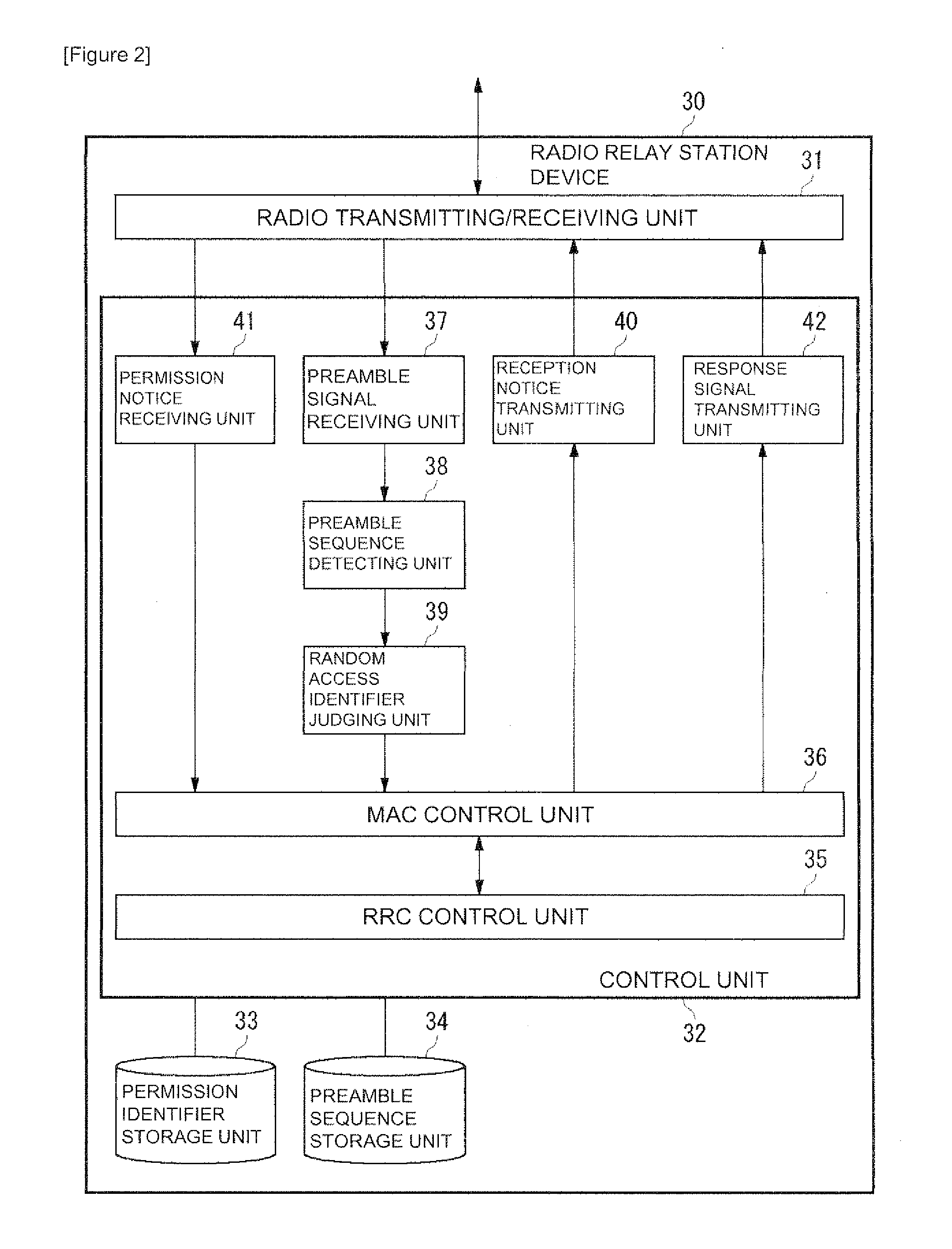
[0069]FIG. 1 is a diagram illustrating a configuration of a radio base station device 10 according to a first embodiment, FIG. 2 is a diagram illustrating a configuration of a radio relay station device 30 according to the first embodiment, and FIG. 3 is a diagram illustrating a radio terminal device 50 according to the first embodiment. In addition, FIG. 4 is a sequence diagram illustrating a random access procedure according to the first embodiment. A random access procedure according to the first embodiment and operations of the radio base station device 10, the radio relay station device 30, and the radio terminal device 50 will now be described with reference to FIGS. 1 to 4.

[0070]Hereinafter, an example will be considered wherein the radio terminal device 50, which exists within the coverage of the radio base station device 10 and is in a standby state (idle mode) in which the radio terminal device 50 is connected to the radio base station device 10, is paged from a network an...

second embodiment

[0099]Next, a second embodiment of the present invention will be described in detail with reference to the drawings. In the first embodiment, a permission to use a sequence of a random access is granted. However, when a radio terminal device 50 having been permitted continuous use of the sequence performs a cell reselection and transmits a RACH preamble signal in a new cell, as illustrated in FIG. 8, it is possible that the radio base station device 10 may also receive the RACH preamble signal in addition to a radio relay station device 30 that manages the new cell.

[0100]A background of the second embodiment will now be described with reference to FIG. 9. A case will be considered where, after an RRC connection request to the radio base station device 10 fails, a radio terminal device 50 selects a cell managed by a radio relay station device 30 through cell reselection and transmits a RACH preamble signal to the selected radio relay station device 30. When the radio base station dev...

third embodiment

[0107]Next, a wireless communication system according to a third embodiment of the present invention will be described. The wireless communication system according to the third embodiment is basically configured the same as the wireless communication system according to the first embodiment. As illustrated in FIG. 11, in the wireless communication system according to the third embodiment, a radio relay station device 30 further comprises a no-response-required notice transmitting unit 43 that transmits a no-random access response-required notice (No-RACH Response Notice) to a radio base station device 10.

[0108]FIG. 12 is a sequence diagram illustrating a random access procedure according to the third embodiment of the present invention. In the second embodiment, a radio relay station device 30 having granted permission by the radio base station device 10 to use a sequence generates a RACH response signal by a MAC control unit 36 upon receiving a RACH preamble signal comprising the s...


PUM


Abstract

A radio base station device comprises: a preamble signal receiving unit (15) that receives a RACH preamble signal transmitted from a radio terminal device; a reception notice receiving unit (16) that receives, from a radio relay station device, a reception notice indicating that the radio relay station device has received the RACH preamble signal; and a response signal transmitting unit (18) which, when an identifier (RA-ID) of the RACH preamble signal transmitted from the radio terminal device matches an identifier comprised in the preamble reception notice transmitted from the radio relay station device, permits the use of an identifier by the radio relay station device and transmits, to the radio terminal device, a RACH response signal (RACH Response) comprising a cell identifier (Cell ID) of a cell managed by the radio relay station device permitted to use the identifier. Accordingly, the latency when establishing a connection can be reduced.

Description

RELATED APPLICATION[0001]The present application is based upon and claims the benefit of priority from Japanese Patent Application No. 2008-165536, filed on Jun. 25, 2008, the disclosure of which is incorporated herein in its entirety by reference.TECHNICAL FIELD[0002]The present invention relates to a wireless communication system comprising a radio base station device (eNodeB), a radio relay station device (Relay Node: also referred to as a Relay Station, a Repeater, and the like), and a radio terminal device (UE). More particularly, the present invention relates to a wireless communication system capable of reducing latency when establishing a communication connection and reducing the period of time until a radio terminal device starts communication.BACKGROUND ART[0003]The recent progress in wider bandwidths and faster data rates in mobile radio communication services has led to the realization of multimedia services such as music and video. With an aim of realizing even faster d...

Claims


Application Information

Patent Timeline
Patent Type & Authority Applications(United States)
IPC IPC(8): H04B7/14H04L12/26
CPCH04B7/155H04J11/0069H04W84/047H04W74/0833H04W74/008H04W74/002
Inventor ISHII, YOSHIKAZUKANAZAWA, TAKESHI
Owner SOVEREIGN PEAK VENTURES LLC
Learn More