
Progressive shock absorbing line device

a line device and progressive technology, applied in the direction of shock absorbers, safety belts, transportation items, etc., can solve the problems of large jarring, unsatisfactory methods, and rapid transmission of force and shock to objects, and achieve the effect of reducing shock

Inactive Publication Date: 2011-05-12
SANFORD ERIC
View PDF13 Cites 6 Cited by
  • Summary
  • Abstract
  • Description
  • Claims
  • Application Information

AI Technical Summary

Benefits of technology

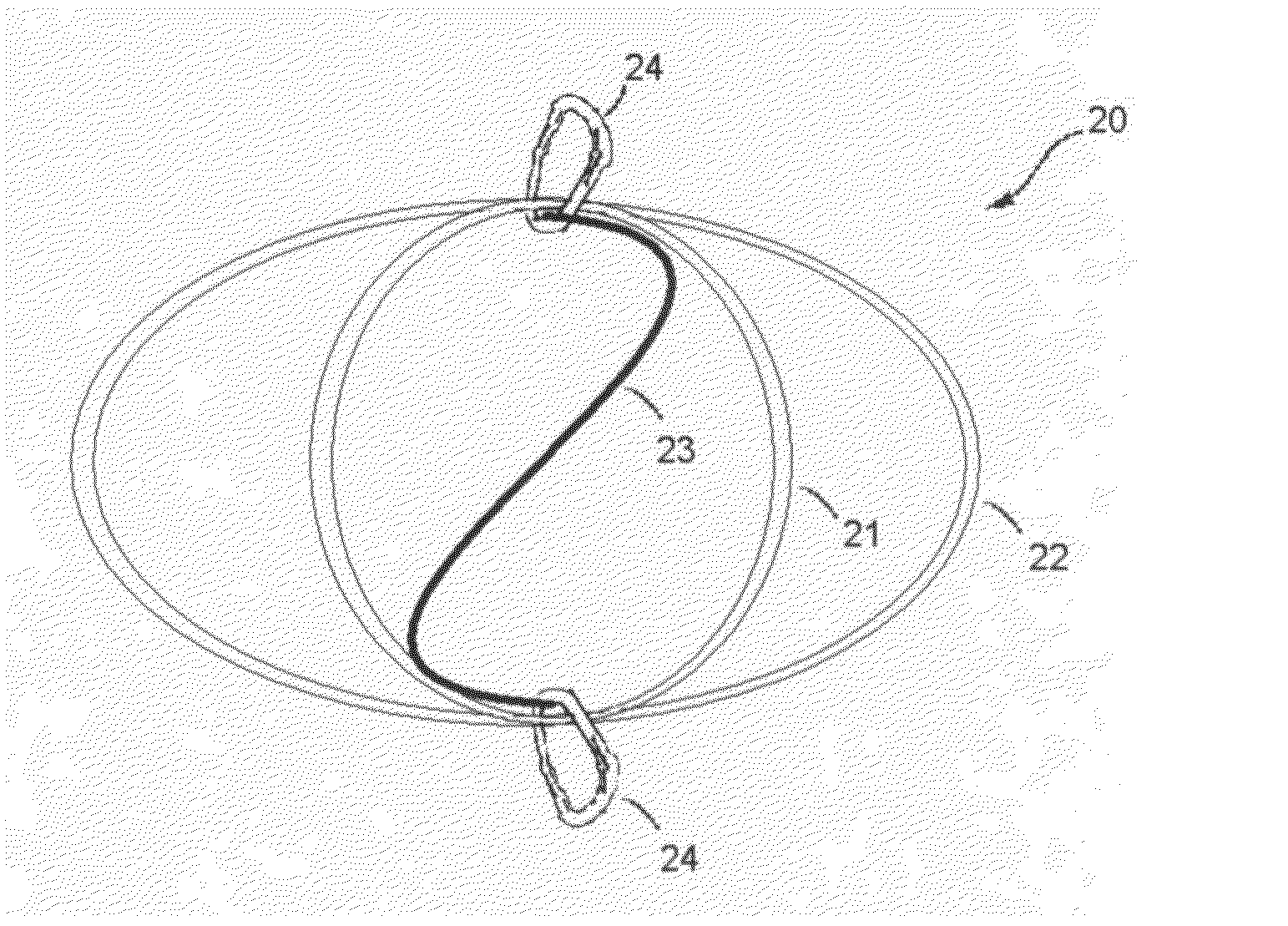
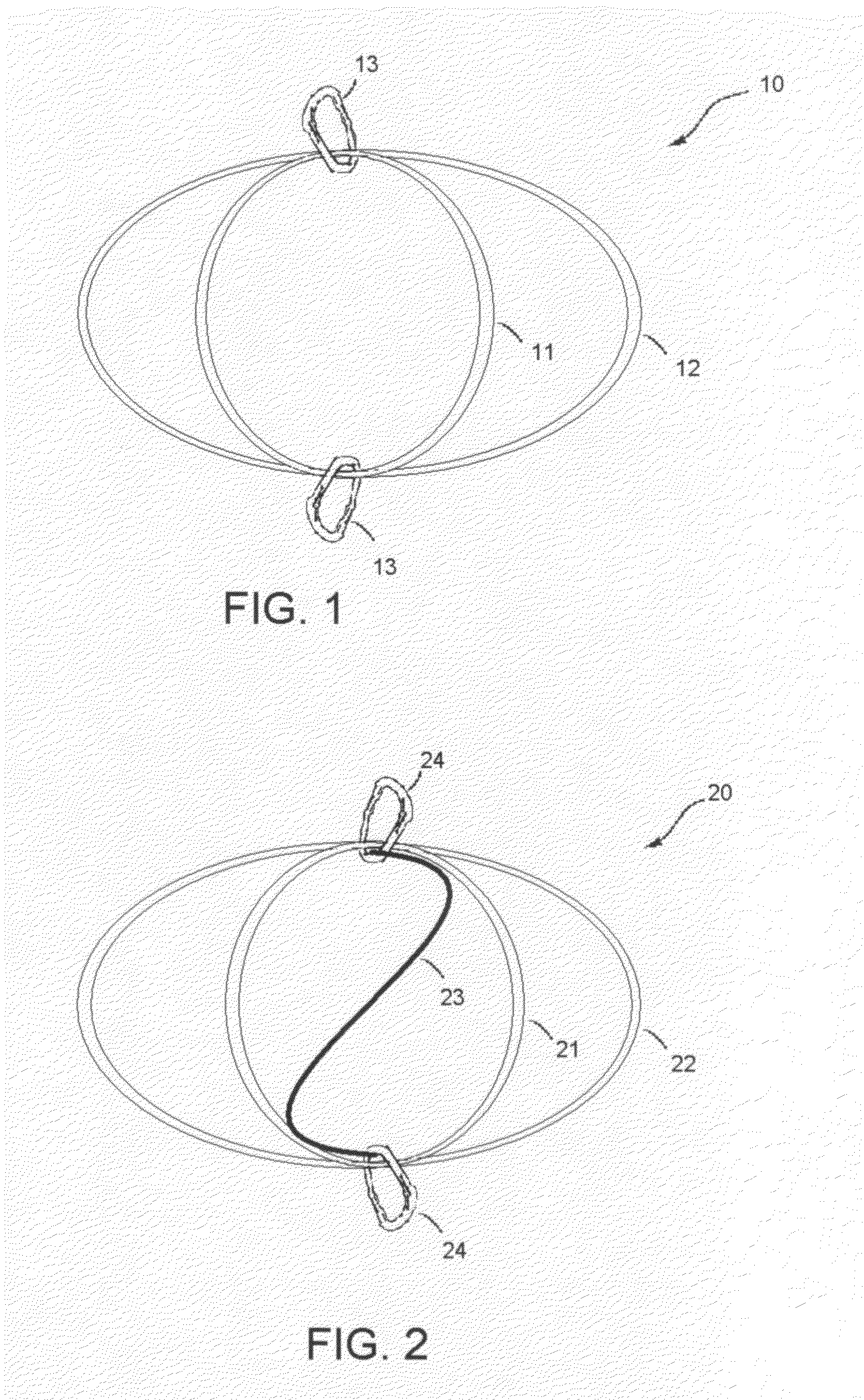
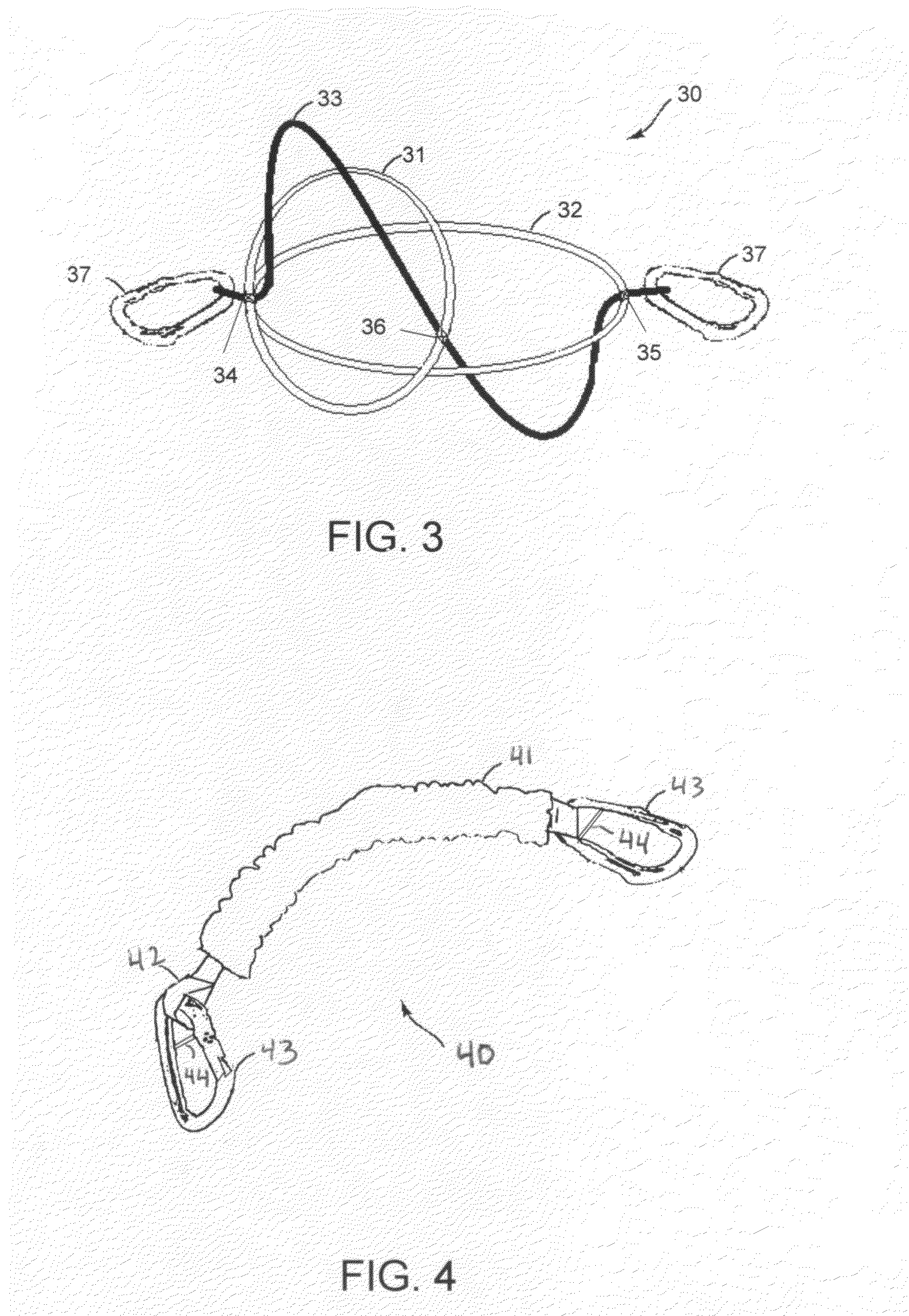
The invention is a shock absorbing line device that includes a first inner resilient component and a second inner resilient component, each with opposing ends. The device has attachment devices for securing it to objects and an internal limiting member for controlling its stretching. The device can reduce shock between objects and has a unique tension range for each distance it is extended. The technical effects of the invention include improved shock absorption, reduced damage to objects, and improved stability and control during use.

Problems solved by technology

While this has the advantage of being flexible and adaptable, there are situations where such methods have undesirable characteristics.
When a rope is used, it becomes slack as the objects move together and allows the objects to move apart without resistance until the slack is taken up, at which point it becomes taut and rapidly transmits force and shock to the objects.
When sufficient forces are involved, this can result in substantial jarring.
However, tying knots in elastic line can be difficult.
Further, elastic lines often exhibit reduced breaking strength as compared to non-elastic lines.
While convenient, bungee cords have their own deficiencies.
Further, typical bungee cords are not often built to handle significant stresses.
As users of such devices are aware, the elastic cord often fails and the hooks deform.

Method used


Image

  • Progressive shock absorbing line device
  • Progressive shock absorbing line device
  • Progressive shock absorbing line device

Examples


Embodiment Construction

[0022]It is to be understood that the terminology used herein is for the purpose of describing particular embodiments of the invention only and is not intended to be limiting.

[0023]Unless defined otherwise, all technical and scientific terms used herein have the same meaning as commonly understood by one having ordinary skill in the art to which the invention pertains.

[0024]Further, all publications, patents and patent applications cited herein, whether supra or infra, are hereby incorporated by reference in their entirety.

[0025]Finally, as used in this specification and the appended claims, the singular forms “a, “an” and “the” include plural referents unless the content clearly dictates otherwise.

[0026]Earlier U.S. Pat. No. 7,032,529 to Sanford discloses a shock absorbing line device and provides details on examples of suitable materials and construction, but does not feature progressive variation in tension. The disclosure of this patent is hereby incorporated by reference in its...


PUM


Abstract

A shock absorbing line device preferably comprising at least two inner resilient components having different working lengths to provide progressive change in the tension developed by the device. The inner resilient components can be formed from one or more loops of shock cord. The use of an internal limiting member restricts the overall extension of the device.

Description

FIELD OF THE PRESENT INVENTION[0001]The present invention relates generally devices for securing to objects together. More particularly, the invention relates to flexible devices for securing objects that are capable of absorbing forces tending to separate the objects.BACKGROUND ART[0002]A common method for securing objects together comprises a simple line or rope. While this has the advantage of being flexible and adaptable, there are situations where such methods have undesirable characteristics.[0003]For example, it is often advantageous to provide a device that is compliant or elastic. Such a device can provide tension between the two objects even when the distance between them changes. In contrast, a simple rope becomes slack once the distance between the objects decreases. Further, the use of an elastic device offers the ability to absorb force or shock as the objects are moved apart.[0004]The lack of these features is often exacerbated when the objects being secured are able ...

Claims


Application Information

Patent Timeline
Patent Type & Authority Applications(United States)
IPC IPC(8): F16F9/00
CPCA01K27/005D07B2401/2005B60P7/0823A62B35/04
Inventor SANFORD, ERIC
Owner SANFORD ERIC
Learn More