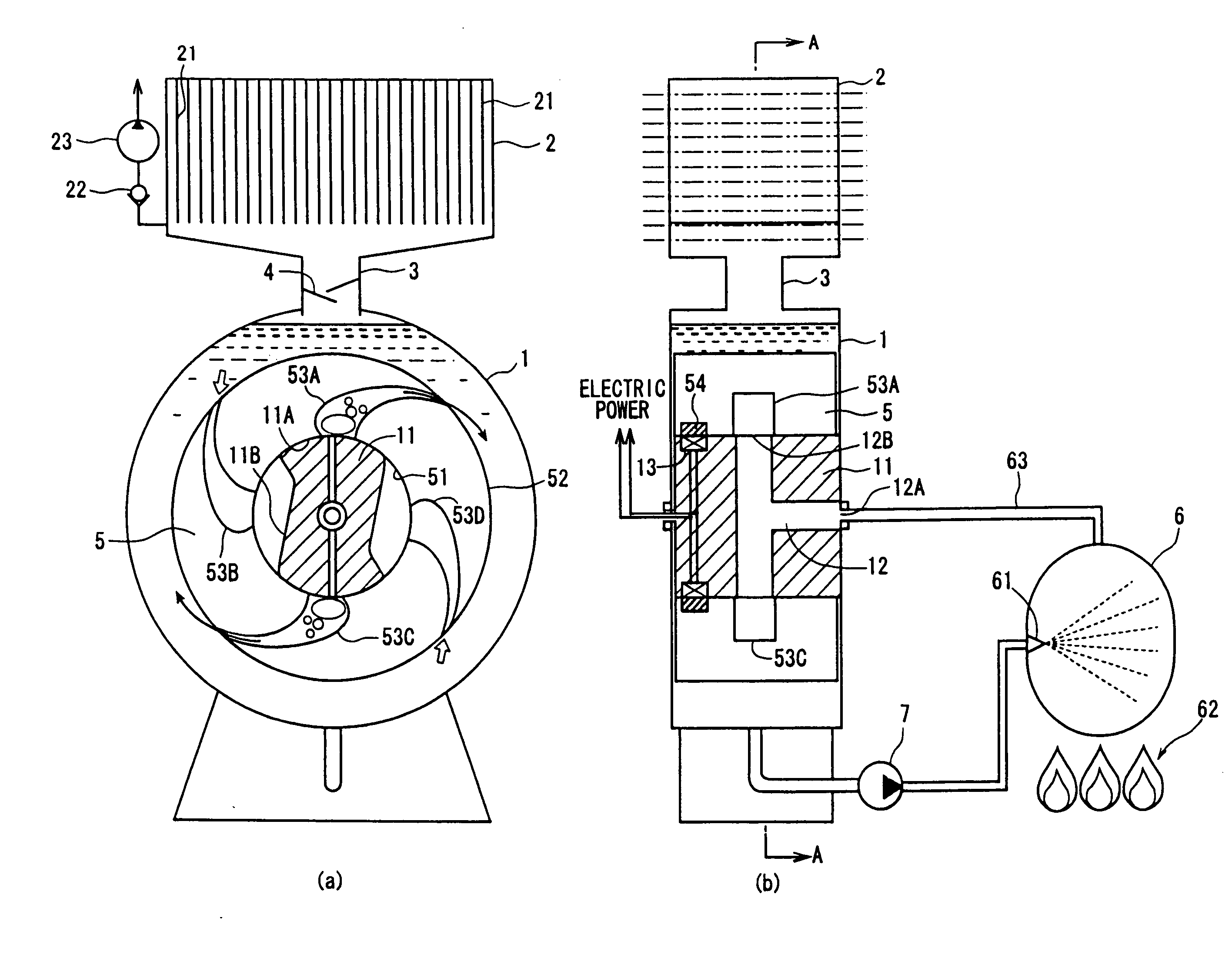
[0018]The steam engine unit of the invention includes the rotor that is rotatably supported in the closed container filled with the liquid, and wherein the liquid in the plurality of bent flow paths formed in the rotor is jetted from the flow paths in the form of a mixture of the liquid and the steam due to the steam generated in the boiler, and the rotor rotates by the reaction thereof. The jetted mixture contains much liquid and its
mass is far greater than that of the steam. Like the steam engine shown in FIG. 4, therefore, a large torque is obtained even at the time when the rotor rotates at low speeds. Therefore, the steam engine body of the invention efficiently operates even at low speeds.
[0019]The rotor in the steam engine body of the present invention has the inner circumferential surface formed in a round shape in cross section, and has the plurality of bent flow paths evenly arranged in the circumferential direction of the rotor and extending from the inner circumferential surface to the outer circumferential surface. The rotor has no moving part such as
check valve, and features a simple structure and high reliability, and is free from inconvenience that may be caused by the effect of
centrifugal force during the rotation. Further, plurality of bent flow paths are evenly arranged in the circumferential direction of the rotor which, therefore, has a point-symmetrical shape in transverse cross section without any unbalanced weight. Therefore, the rotor of the invention has excellent static or
dynamic balance.
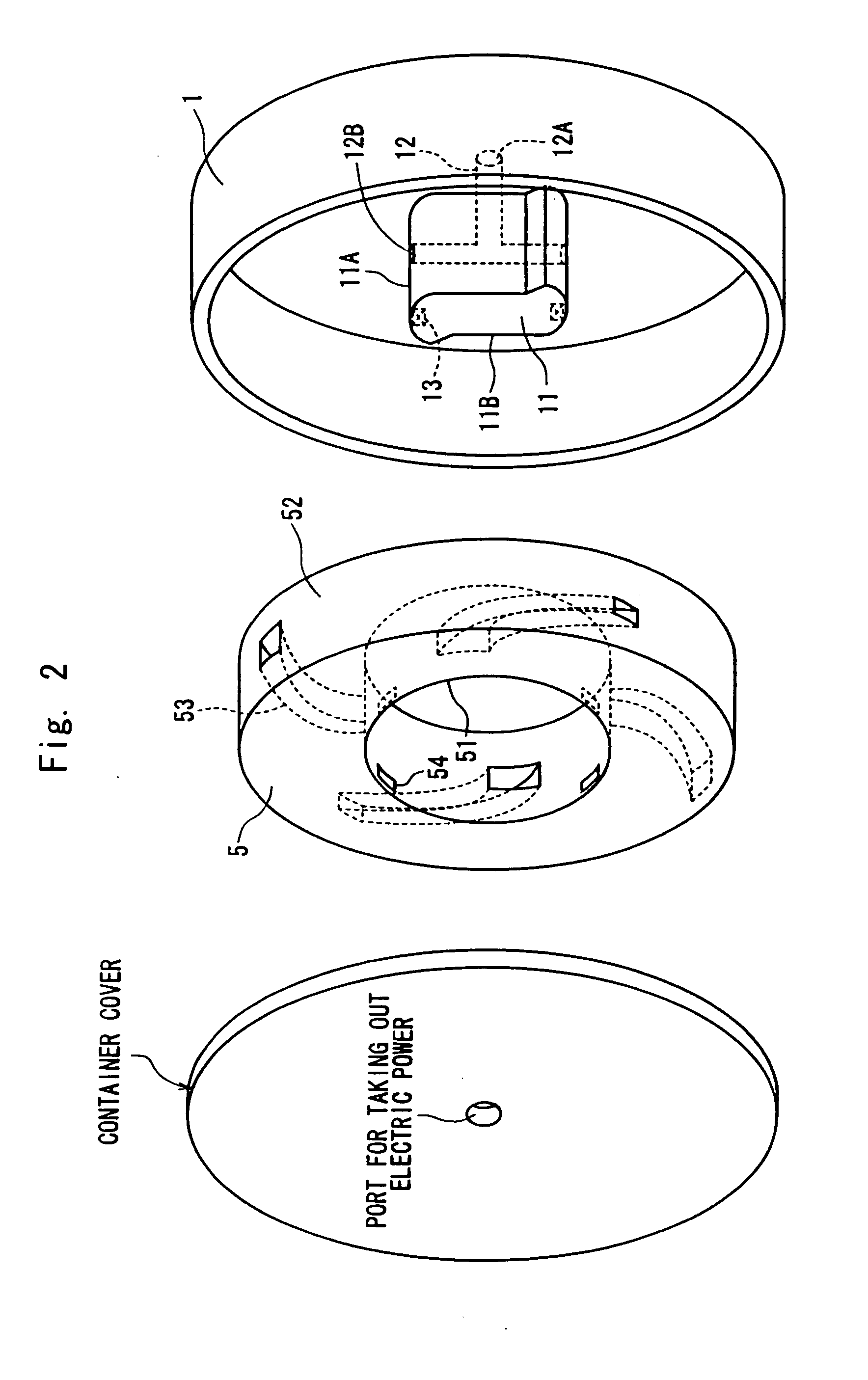
[0020]Moreover, the rotor of the invention is rotatably supported being fitted onto the boss portion that is fixed to the side wall of the closed container, and the outer periphery of the boss portion is alternately forming slide-contact portions on where the inner circumferential surface of the rotor slides in contact therewith and recessed portions from where the inner circumferential surface of the rotor separates away. The slide-contact portions are provided with a steam feed port for introducing the steam generated in the boiler into the rotor. When the bent flow path of the rotor is opened to the steam feed port, the steam flows into the bent flow path and is jetted from the outer periphery of the rotor together with the liquid in the flow path to impart a rotational torque to the rotor.
[0021]As the rotor rotates and the communication is interrupted between the bent flow path and the steam feed port, the liquid in the surrounding flows reversely into the bent flow path through the opening on the outer circumferential side of the rotor imparting torque to the rotor in a direction in which the rotational torque increases. Here, the steam remaining in the bent flow path is liquefied upon being cooled by the surrounding liquid of a low temperature. Here, if the cooling is not sufficient, the rotor rotates with the steam remaining therein, and the bent flow path is opened to the steam feed port again. The liquid, therefore, is jetted in decreased amounts and only a decreased rotational torque is produced. According to the present invention, recessed portions are formed in the outer circumference of the boss portion onto which the rotor is fitted and after the communication is interrupted between the bent flow path and the steam feed port accompanying the turn of the rotor, the bent flow path opens in the recessed portion. The liquid of a low temperature is present in the recessed portions and, therefore, the remaining steam is cooled thereby and, besides, the steam partly flows into the recessed portion, and the steam remaining in the bent flow path substantially disappears. As a result, when the bent flow path opens to the steam feed port again, the interior of the flow path has been filled with the liquid, and the steam engine operates efficiently.
[0022]The invention of claim 2 is concerned to the steam engine unit, wherein a
circulating pump is provided to feed the liquid in the closed container to the boiler, an injection
nozzle is provided in the boiler, and the liquid is injected in an atomized form into the boiler. Usually, the operation fluid is continuously fed in the
liquid state into the boiler of the steam engine unit and is transformed into the steam upon being heated. However, a considerable period of time is necessary to evaporate the liquid that is continuously fed, and the starting time is prolonged before power is generated. According to the invention of claim 2, the liquid is injected in an atomized form into the boiler from the injection
nozzle provided in the boiler, and the time for evaporating the liquid is greatly shortened. Therefore, start performance of the steam engine unit is improved, quick response is attained even when the load has increased, and characteristics required for the vehicle can be satisfied.
[0023]The invention of claim 3 is concerned to the steam engine unit of the present invention, wherein a condenser is provided being communicated with the closed container to condense the steam. The closed container of the present invention is placed in the
atmosphere and radiates heat to the surrounding. Therefore, the closed container itself can be used as a so-called low heat source. Upon providing a condenser communicated with the closed container and introducing the steam in the closed container to the condenser, however, the steam can be efficiently condensed and the efficiency of the steam engine unit as a whole can be improved.


