Composite glass seal for a solid oxide electrolyser cell stack
a solid oxide electrolyser and glass seal technology, applied in the direction of fuel cell details, electrolysis components, chemistry apparatus and processes, etc., can solve the problems of corrosion of glass seals, electrode performance declines over time, and none of them have been able to meet all mechanical performance requirements
- Summary
- Abstract
- Description
- Claims
- Application Information
AI Technical Summary
Benefits of technology
Problems solved by technology
Method used
Image
Examples
example 1
Seals Prepared by Two Step Screen Printing
[0066]Step 1: Screen Printing of the Glass Component (4a)
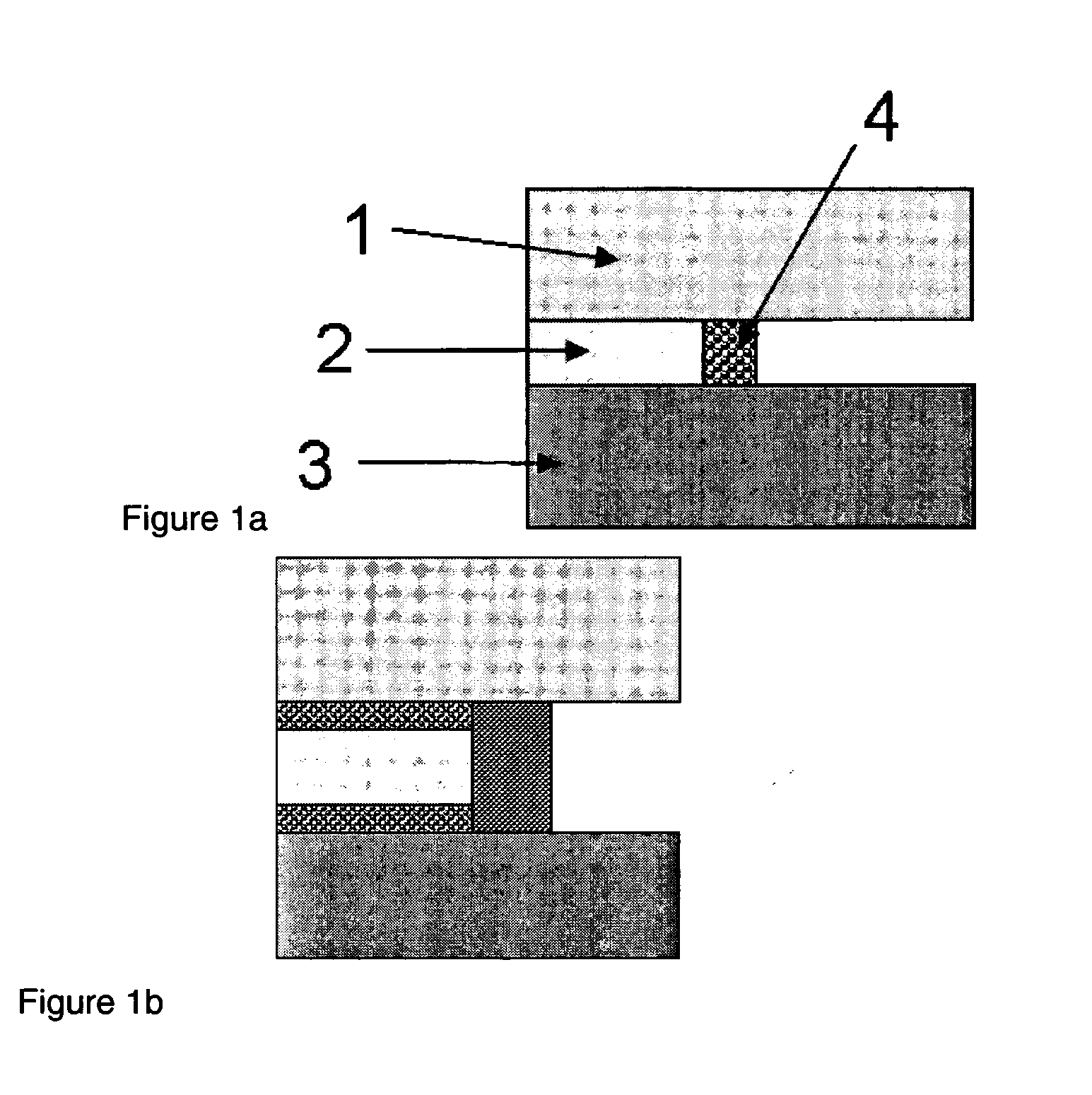
[0067]A screen printing ink is prepared from the glass powder CAS-1 by suspending the powder in terpineol together with a binder, a plasticizer and a dispersant. Glass is printed on the outer part of the sealing area, covering about ¾ of the width of the sealing area to be sealed.
Step 2: Preparing the Metal Oxide Component (4b)
[0068]Nanocrystalline SrO powder is prepared with crystal sizes of about 30 nm by precipitating from a Sr(NO3)2 solution.
Step 3: Screen Printing the Metal Oxide Component (4b)
[0069]The metal oxide powder mixture prepared in step 2 is suspended in solution with a solvent (terpineol), a binder, a dispersant and a plasticizer. This ink is printed on the inner edge of the sealing area, covering the ¾ of the area that was not covered by component 4a. Thus the sink material is located next to the glass on the side towards the cell and the gas passage ways.
example 2
Seals Prepared by Spraying and Screen Printing
[0070]Step 1: Preparing Metal Oxide Component (4b)
[0071]Preparing as in example 1 step 2.
Step 2: Applying the Metal Oxide Component (4b) by Spraying
[0072]The metal oxide component is suspended in a solvent with a binder to produce a sprayable ink. The ink is sprayed onto the whole area of sealing. A highly porous layer is applied such that the sintered thickness, not applying a weight, would be approximately 50% thicker than the preferred sealing thickness.
Step 3: Applying the Glass (4a)
[0073]The glass is screen printed on top of component 4b on the outer ¾ of the full sealing width. The final seal is illustrated in FIG. 1b.
example 3
Seals Prepared by Screen Printing Having a Backbone in the Porous Structure
[0074]Step 1: Preparing Metal Oxide Component and Backbone (4b)
[0075]Alumina particles were mixed with SrO.
Step 2: Applying the Metal Oxide Component (4b) and the Backbone
[0076]A screen printing ink was prepared with the mixed powder and was screen print on the inner ¼, as in Example 1.
Step 3: Screen Printing the Glass (4a)
[0077]The glass is screen printed as in example 1 on the outer ¾ of the sealing width.
PUM
| Property | Measurement | Unit |
|---|---|---|
| porosity | aaaaa | aaaaa |
| temperatures | aaaaa | aaaaa |
| thickness | aaaaa | aaaaa |
Abstract
Description
Claims
Application Information
 - R&D
- Intellectual Property
- Life Sciences
- Materials
- Tech Scout
- Unparalleled Data Quality
- Higher Quality Content
- 60% Fewer Hallucinations
Browse by: Latest US Patents, China's latest patents, Technical Efficacy Thesaurus, Application Domain, Technology Topic, Popular Technical Reports.
© 2025 PatSnap. All rights reserved.Legal|Privacy policy|Modern Slavery Act Transparency Statement|Sitemap|About US| Contact US: help@patsnap.com


