
Method and apparatus for solar panel tracking

a solar panel and tracking method technology, applied in the direction of instruments, lighting and heating apparatus, sustainable buildings, etc., can solve the problems of poor sun tracking performance, large flat “billboard” sized solar panels, unattractive residential purposes, etc., to improve the tracking ability and improve the accuracy.

Inactive Publication Date: 2011-04-28
JONES DALE G +1
View PDF16 Cites 36 Cited by
  • Summary
  • Abstract
  • Description
  • Claims
  • Application Information

AI Technical Summary

Benefits of technology

[0007]Because of differences in sun position with respect to the horizon at different geographical latitude locations on the earth, it is also desirable to provide a second solar panel position starting point input, which can be used to improve and refine the tracking ability because adjustments programmed within the ROM chip can be set up to account for latitude locations if a second input is provided. For example, another such input signal can be established by aiming the solar panels directly towards the sun at some other known time which is several hours different from solar noon. Once at least two such points are established, the sun tracking system of the present invention enables the solar panels to track the sun with improved accuracy which compensates for different geographic latitude locations.
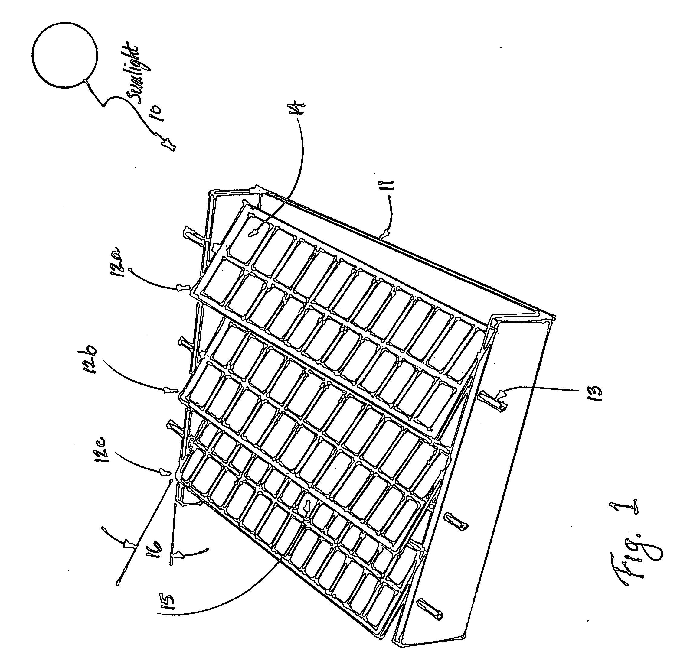
[0008]Another feature of the present invention is to provide a very low-profile solar panel array which lies flat with the surface of almost any type of roof or structure. This eliminates the need to have large “billboard” size solar panels which are aesthetically unpleasing and objectionable for use in most residential areas. The physical appearance of such solar panel arrays would be much more acceptable for use in residential applications, because they would appear to be roof vents, skylights, or louvers.

Problems solved by technology

However, large flat “billboard” sized solar panels are both unattractive for residential purposes and also require expensive structural mounting equipment, especially in high wind loading areas.
Both such systems suffer the disadvantages of (a) poor sun tracking performance caused by dirt, bird droppings, or other material that might collect on the photocell sensors or the collector tubes, and (b) relatively expensive structural members designed to provide the necessary rotating capability for a relatively large flat solar panel array, generally at least about 4×6 feet in size, but perhaps as much as 12×18 feet in size.

Method used


Image

  • Method and apparatus for solar panel tracking
  • Method and apparatus for solar panel tracking
  • Method and apparatus for solar panel tracking

Examples


Embodiment Construction

[0019]As already shown in FIG. 1, the preferred embodiment for solar panel arrays of the present invention is to arrange long rectangular solar panels in an array like a shutter or a Venetian blind, with the longitudinal axis, 13, of the solar panels, 12a, 12b and 12c, to be aimed directly South, and being enabled to rotate about the longitudinal axis from East to West during daylight hours to thereby track the movement of the sun.

[0020]A diagram of such a sun tracking module is shown in FIG. 2, which provides one preferred embodiment of the present invention. As shown in FIG. 2, there are 9 solar panels, 20a through 20i, arranged in a modular frame, 21, with outside dimensions of 24 by 48 inches, i.e. 2×4 feet, which fits with most of the roof framing dimensions used in the United States. Each solar panel is approximately 4.3 inches wide by 21.8 inches long, and contains 30 solar PV cells connected in series, each cell about 4.0×0.7 inches in size, with a total of about 84 sq.in. o...


PUM


Abstract

A method for tracking the movement of the sun from East to West across the sky during daylight hours to enable solar photovoltaic (PV) panels or arrays of such panels to capture significantly more solar energy than fixed solar panels. Readily-available sun position data (taken from ephemeris or celestial navigation tables) can be programmed into read-only memory (ROM) chips. Date and time of day information can also be programmed into ROM chips powered by long-life, rechargeable batteries, such as lithium-ion batteries. Using such ROM chip data, a solar panel or an array of solar panels can track the sun position provided that during installation (with the panels aimed longitudinally towards the South), the solar panels are positioned upwards towards the noontime sun position to establish a starting point. This enables the sun tracking system of the present invention to track the sun without requiring a solar sensing device. Sun tracking provides an increase of from about 20% to 50% increased solar energy capture compared with fixed, non-tracking solar panels. Experimental data is also provided to illustrate the effectiveness of the present invention.

Description

CROSS-REFERENCE TO RELATED APPLICATION[0001]This application claims priority from provisional application No. 60 / 555,694 filed Mar. 24, 2004, which is incorporated herein in its entirety by this reference.FIELD OF THE INVENTION[0002]The present invention relates to tracking the movement of the sun from East to West across the sky during daylight hours to enable solar photovoltaic (PV) panels, or arrays of such panels to capture significantly more solar energy than fixed solar panels. Readily-available sun position data (taken from ephemeris or celestial navigation tables) can be programmed into read-only memory (ROM) chips. Date and time of day information can also be programmed into ROM chips powered by long-life, rechargeable batteries, such as lithium-ion batteries. Using such ROM chip data, a solar panel or an array of solar panels can track the sun position provided that during installation (with the panels aimed longitudinally towards the South), the solar panels are positione...

Claims


Application Information

Patent Timeline
IPC IPC(8): F24J2/00F24J2/38F24S50/20
CPCY02B10/20Y02E10/47Y02E10/50F24J2/541H01L31/042F24J2/38F24S30/425F24S50/20G01S3/7861H02S20/32
Inventor JONES, DALE G.MARCUM, BARBARA L.
Owner JONES DALE G
Learn More