
Method for virtual bass synthesis

Inactive Publication Date: 2011-04-21
NAT CHIAO TUNG UNIV
View PDF2 Cites 21 Cited by
  • Summary
  • Abstract
  • Description
  • Claims
  • Application Information

AI Technical Summary

Benefits of technology

[0006]The object of the present invention is to provide a method for virtual bass synthesis, which could attain the virtual bass effect on an ordinary speaker, protect the lifespan of the speaker, reduce the cost, and reduce the operations without causing distortion.
[0012]Moreover, the synthesis method in a preferred embodiment according to the present invention further includes the reduction of sampling frequency of the bass signal implemented by the digital signal processor to simplify the modulation, and the increasing of sampling frequency of the harmonics to pass through a second low pass filter to remove the high frequency noise, and precisely synthesize the harmonics and the remaining portions of the audio signal after abstraction of bass signal to generate a virtual bass audio, wherein the frequency of the audio signal for the bass signal is within a range below 120 Hz.
[0013]Because the present invention uses multiple harmonics to generate the bass with different weights, and reduce the sampling frequency to reduce the operation structure, which could use the non-bass speaker, such as panel speaker or ordinary low-end speaker, to attain the virtual effect. Thus, the present invention could protect the lifespan of the speaker and reduce the cost, and also reduce the operation without distortion.

Problems solved by technology

The ordinary speaker could not have good performance on the low frequency audio signal.
However, the previous method will usually reduce the lifespan of the speaker due to the nonlinear distortion and physical damage.
And, with the additional virtual bass speaker, it will have the defects of larger volume and higher cost, so it is not practical.
However, this method will give inappropriate weights to each harmonic signal, and cause the large distortion for the sound, and this method for enhancing audio signal needs a lot of operations, which causes the heavy loading to the processor.

Method used


Image

  • Method for virtual bass synthesis
  • Method for virtual bass synthesis
  • Method for virtual bass synthesis

Examples


Embodiment Construction

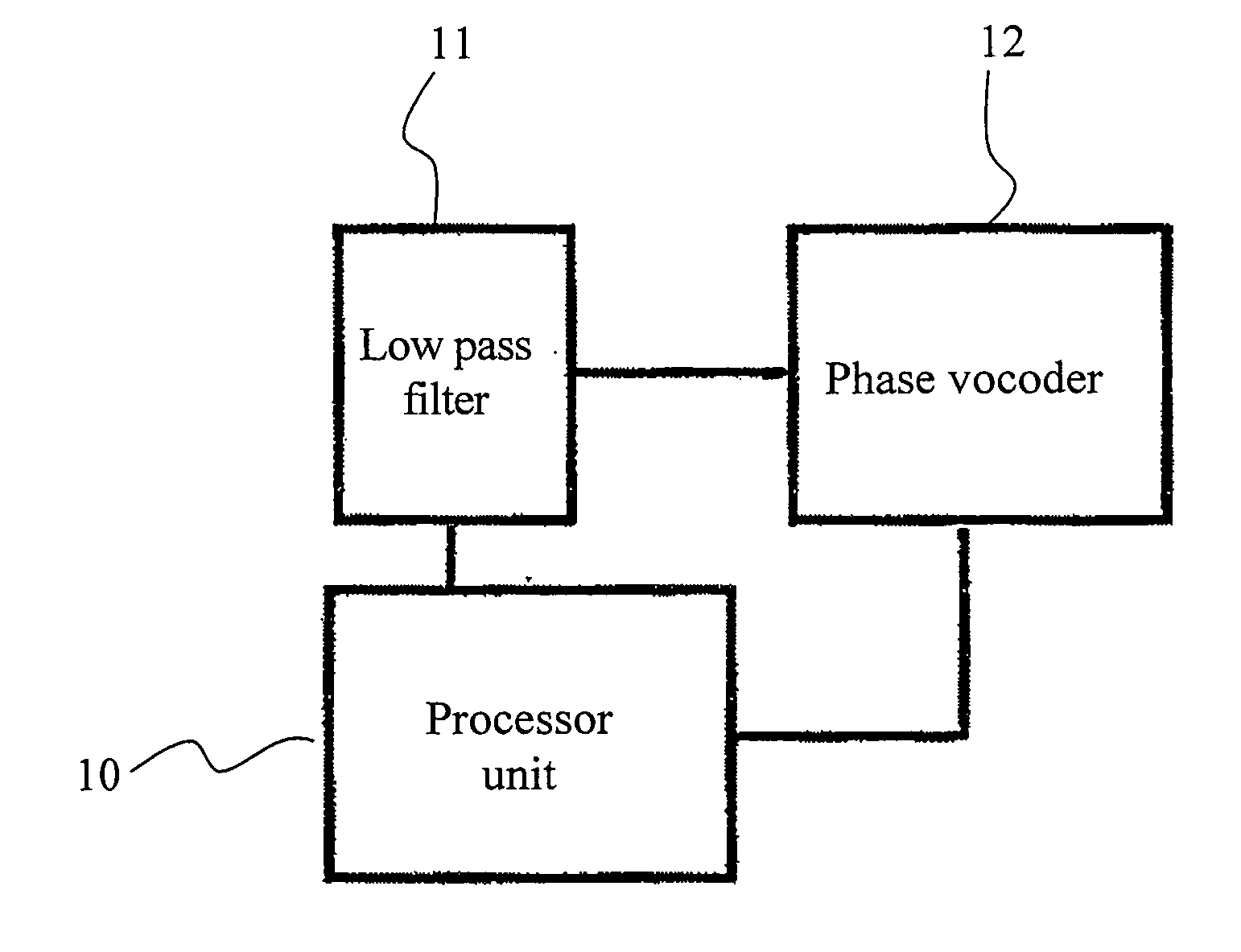
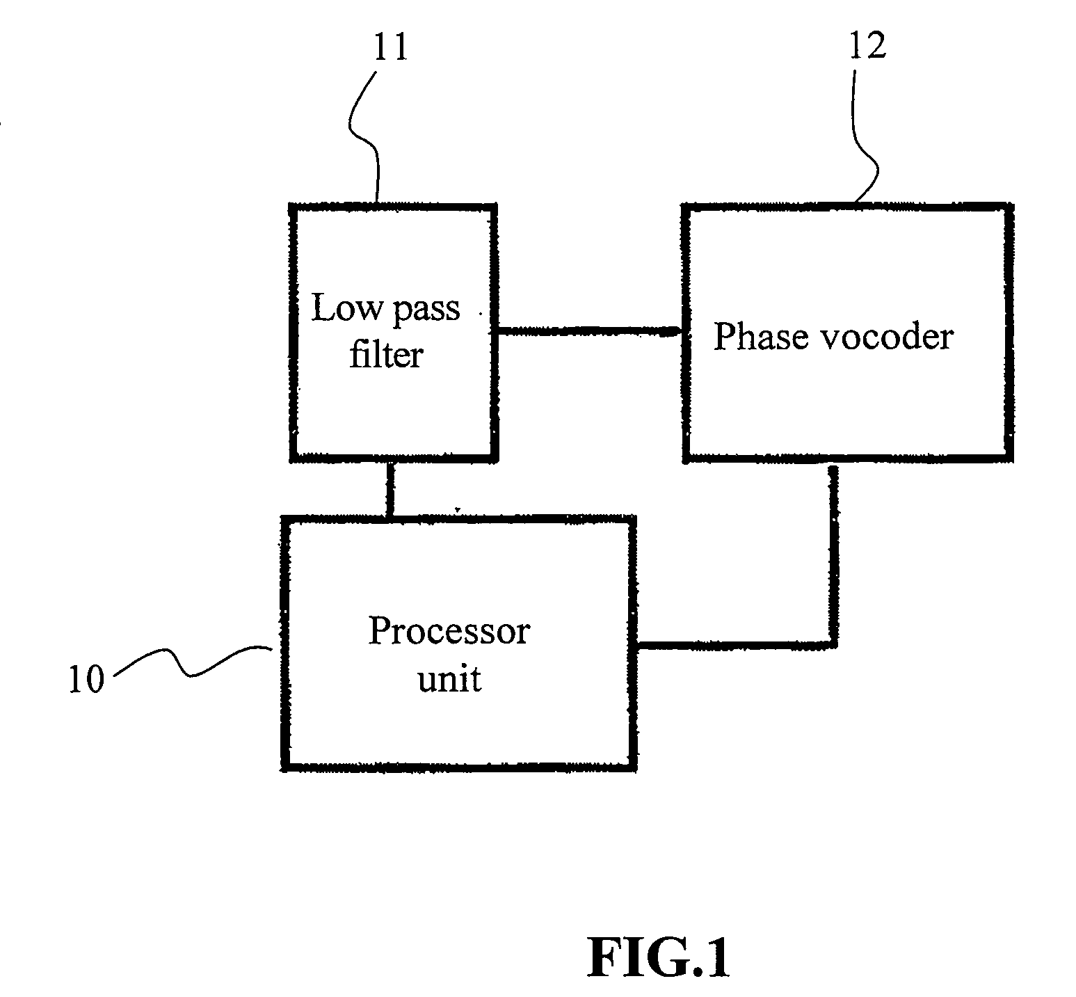
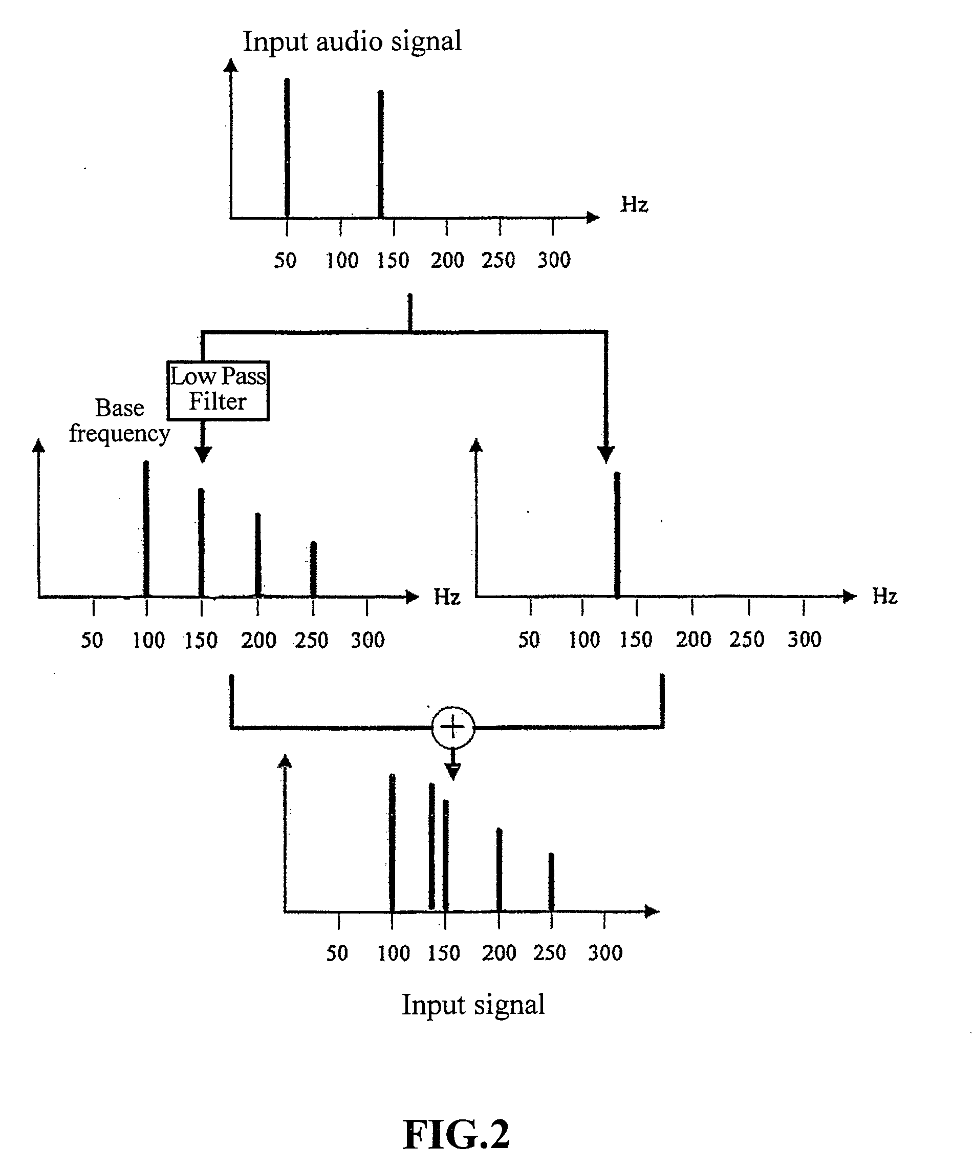
[0023]Please refer to FIG. 1 together with FIG. 2. FIG. 1 illustrates a system block diagram of the method for virtual bass synthesis in an embodiment according to the present invention. FIG. 2 illustrates a frequency distribution diagram of the method for virtual bass synthesis in an embodiment according to the present invention. When the input audio signal is a signal of 50 Hz and 130 Hz, the input audio signal will be passed through a low pass filter 11 by a digital signal processor 10 to attain a 50 Hz low frequency signal at the low pass frequency band. The high pass frequency band is for 130 Hz signal. The frequency of the audio signal for bass signal is within a range equal and below 120 Hz. The method uses the phase vocoder 12 to attain a 50 Hz related harmonic sequence, and modulate the bass signal into harmonics with frequencies at 100 Hz, 150 Hz, 200 Hz, and 250 Hz. The phases of the harmonics should be the same as these of the original bass signal to achieve the effect w...


PUM


Abstract

This invention relates to a method for virtual bass synthesis. The low frequency signal is attained by applying a low pass filter to the original. In order to reduce the operations, process of down sampling the low frequency signal, moving the low frequency signal to a series of harmonics whose frequencies are integral times as large as the frequency of low frequency signals, and then up sampling them are provided. By means of psycho-acoustic theory, the weights of harmonics are attained and applied to the harmonics. Finally the weighted harmonics are combined to produce the bass signal. As the result, the virtual bass effect which is almost the same as the low frequency of the original audio signal can be accomplished. Because the harmonic signals are high frequency ones, the virtual effect can be made in the panel speakers or ordinary low-end speakers.

Description

CROSS REFERENCE TO RELATED APPLICATION[0001]This is a continuation in part of U.S. patent application Ser. No. 11 / 523,412, filed Sep. 19, 2006.TECHNICAL FIELD[0002]The present invention relates to a method for audio synthesis, and particularly to a method for virtual bass synthesis.BACKGROUND OF THE INVENTION[0003]Recently, to enjoy the audio / video entertainment becomes more and more important in human life. Those equipments, such as digital TV, MP3 player, handset, home theater, etc., not only should provide the ordinary sound effect functions, but also become more and more important to provide the additional special sound effect, and the performance of virtual bass is one of the important subject.[0004]The ordinary speaker could not have good performance on the low frequency audio signal. In the past, in order to have the compact speaker or desktop multimedia speaker presenting virtual bass effect, it should increase the gain of low frequency signal, or add an additional virtual b...

Claims


Application Information

Patent Timeline
IPC IPC(8): H04B15/00
CPCG10H1/0091G10H2250/471G10H2210/321H04R3/04H03G9/005
Inventor BAI, MINGSIAN R.TSENG, WEN-LIANGLIN, WAN-CHI
Owner NAT CHIAO TUNG UNIV
Learn More