
Uniformity in slide scanning

a scanning and slide technology, applied in the field of scanning slides, can solve the problems of non-uniform image intensity, large defocusing, and deviation from flatness, and achieve the effect of improving the uniformity of slide scanning, effective and economical manner

Inactive Publication Date: 2011-04-21
MOLECULAR DEVICES
View PDF5 Cites 10 Cited by
  • Summary
  • Abstract
  • Description
  • Claims
  • Application Information

AI Technical Summary

Benefits of technology

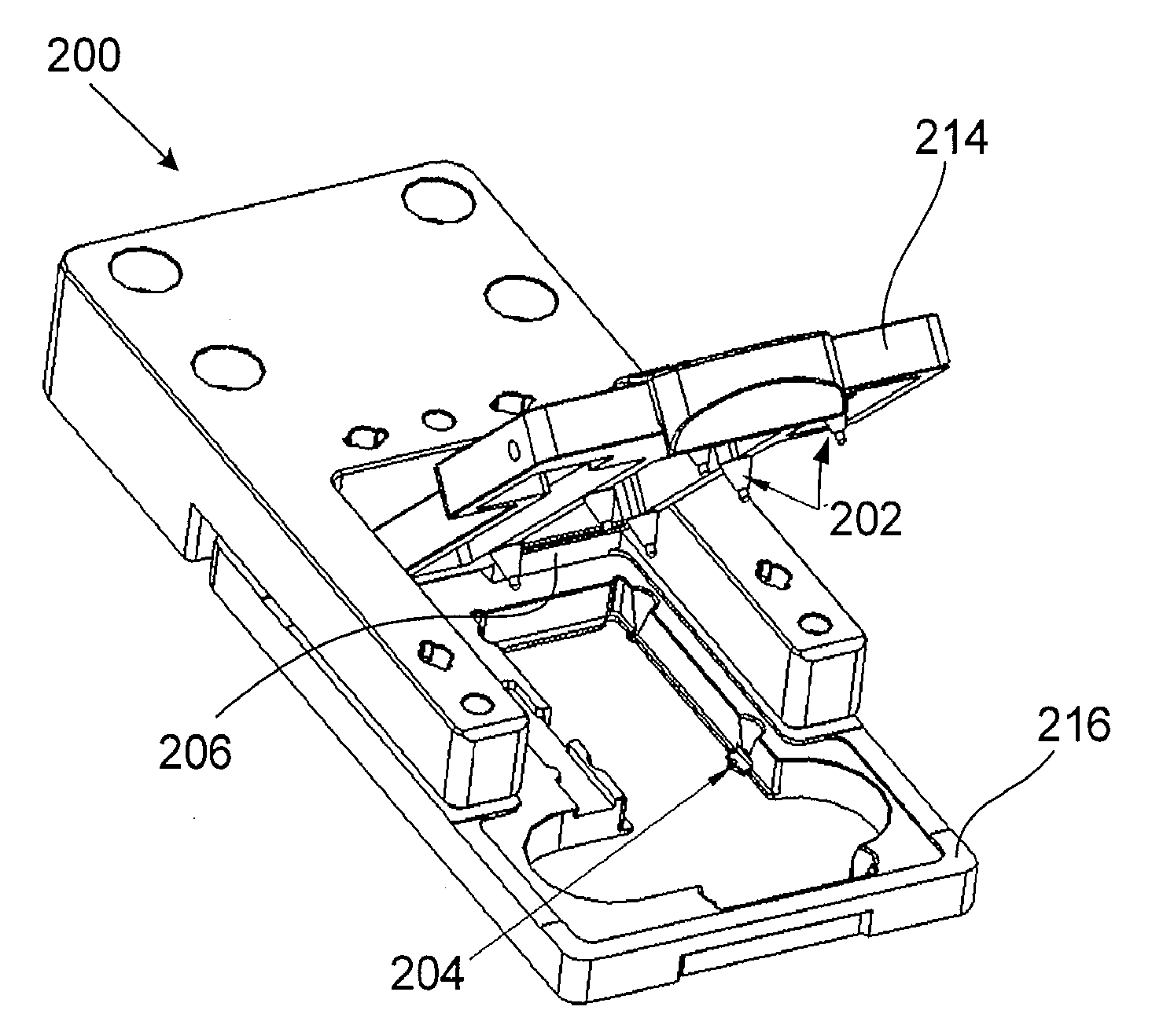
The invention is a new slide stage and methods for holding and deforming non-planar slides in a slide scanner. The slide stage includes at least four fixed members that are arranged at the focal plane of the slide stage and at least four compression members that apply a controlled force to the surface of the slide. This allows for secure holding and deformation of the slide without cracking it. The method involves inserting the slide into the slide stage and applying a controlled force to at least four points on the surface of the slide. The technical effects of this invention include improved uniformity in slidescanning, reduced manufacturing irregularities, and improved efficiency in slide scanners.

Problems solved by technology

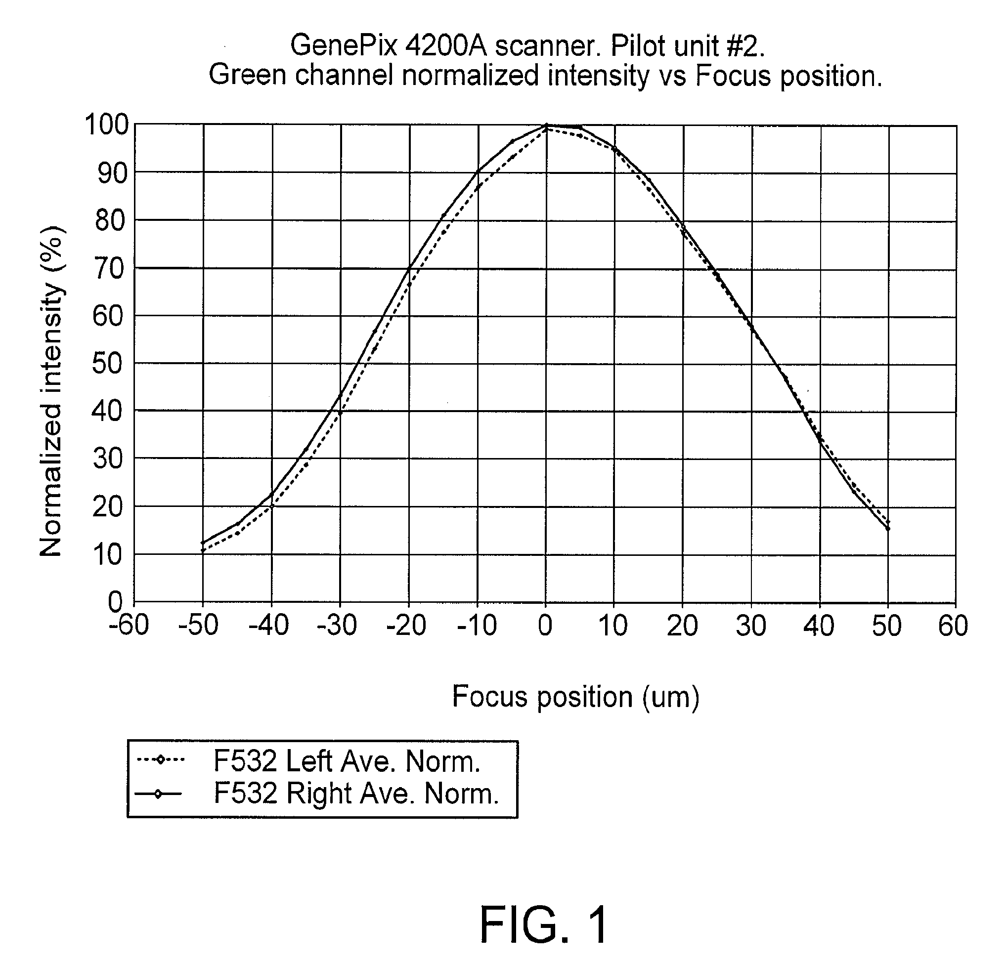
However, most slides used in practice deviate significantly from flatness by typically tens or even hundreds of micrometers, and even slides promoted as “optically flat” can typically deviate from flatness by tens of micrometers.
During scanning, this deviation from planarity results in substantial defocusing and non-uniformity of the image intensity.
Both defocusing and non-uniformity are detrimental for scanner performance.
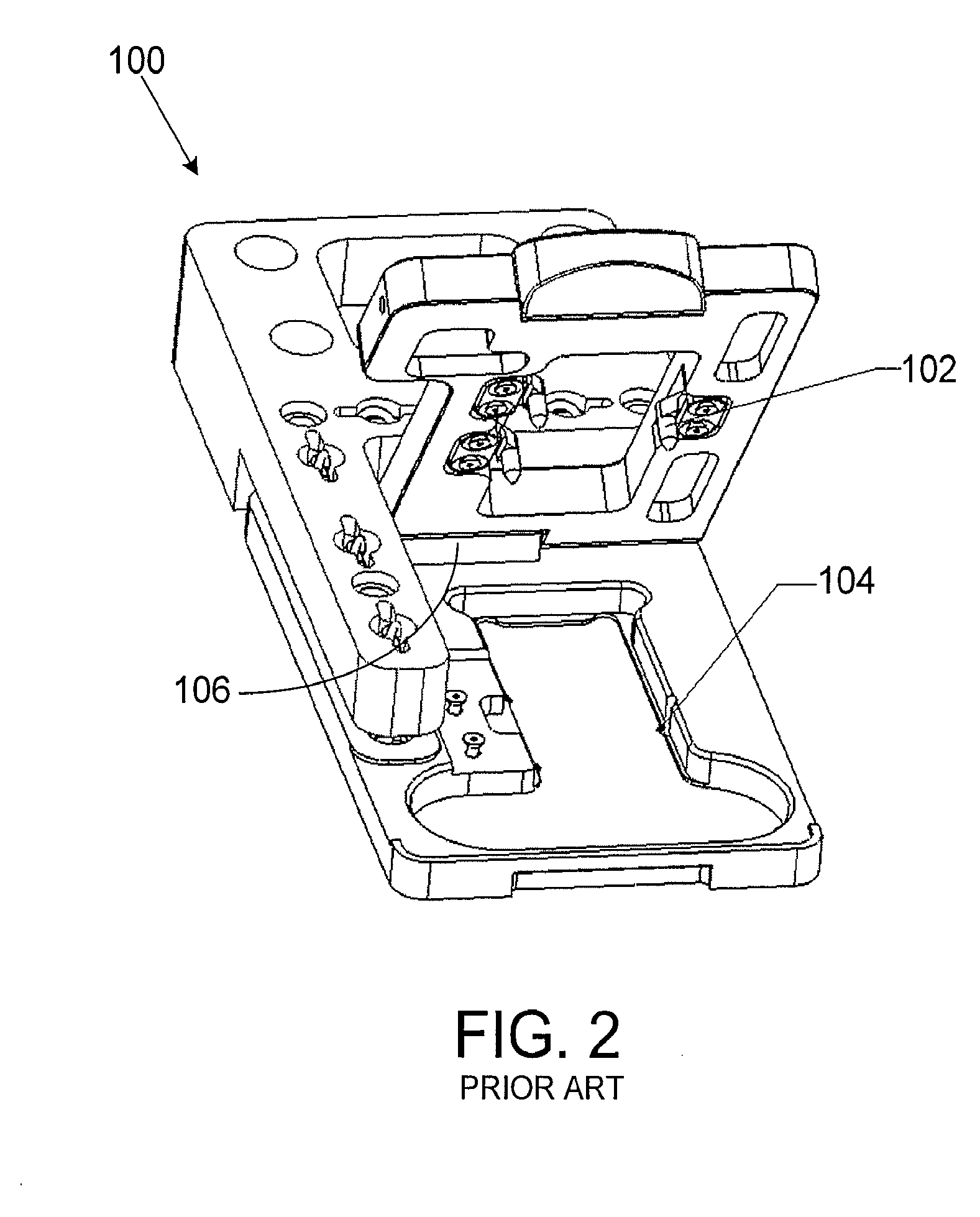
However, slide stage 100 does not address the issues that arise with non-planar slides, as indicated in FIGS. 3A and 3B.
However, such strategies can involve a mechanical system that adjusts slide position to compensate for this deviation, additional optics to measure deviation of the slide surface from the focal plane during scanning, and associated control circuitry, which can increase cost and can require additional service and calibration.
In addition, attempts to resolve the issue have also resulted in systems that can crack the sample slides.

Method used


Image

  • Uniformity in slide scanning
  • Uniformity in slide scanning
  • Uniformity in slide scanning

Examples


example 1

FIG. 7A shows the deviation from planarity of an unrestrained / uncompressed non-planar slide as measured by interferometry. Resulting peak-to-valley (PV) non-planarity was measured at 3.65 micrometers.

FIG. 7B, by contrast, shows the same non-planar slide as positioned in the six-point slide stage 201 depicted in FIGS. 6A and 6B. On compression in six-point slide stage 201, interferometry showed that the unrestrained non-planarity of 3.65 micrometers of the slide was reduced to 1.76 micrometers. This deformation towards the focal plane is sufficient to lead to a measurable improvement in focus and uniformity.

example 2

FIG. 8A shows the deviation from planarity of a substantially non-planar (warped) slide as measured by interferometry in an unrestrained / uncompressed state. The peak-to-valley (PV) non-planarity was estimated to be 30-40 micrometers. Interferometry was not capable of measuring planarity along the long side of the slide, because of the very high density of the interference fringes. The central part of the slide (½ of the length) was measured to be non-planar by about 9 micrometers.

FIG. 8B, by contrast, shows the same non-planar slide as positioned in the six-point slide stage 201 depicted in FIGS. 6A and 6B. On compression in six-point slide stage 201, interferometry showed that the estimated unrestrained non-planarity of 30-40 micrometers was reduced to 6.98 micrometers for the entire slide. This deformation towards the focal plane led to a substantial improvement in focus and uniformity.


PUM


Abstract

A sample slide stage includes at least four fixed members that are arranged at, or about at, a focal plane of the slide stage, and are configured to receive a slide; and a plurality of compression members that apply a controlled force to compress a slide towards the fixed members at the focal plane, whereby a surface of a non-planar slide in the sample stage is deformed towards the focal plane. Methods of deforming non-planar slides towards a focal plane include inserting a non-planar slide into a sample slide stage that has at least four fixed members arranged at or about at a focal plane; and applying a controlled force to compress the non-planar slide to the fixed members at the focal plane, whereby a surface of the non-planar slide is deformed towards the focal plane.

Description

TECHNICAL FIELDThis invention relates to scanning of slides, and more particularly to improving uniformity in scanning of slides.BACKGROUNDScanning of biological samples, e.g., microarray slides, typically involves scanning the slide in two dimensions. For example, a slide mounted in a slide holder of an optical scanning stage can be moved relative to each other by a Y-axis translation stage, which can advance a step for each line scanned in an X-axis translation stage. The optical scanning stage can direct light, e.g., from a laser, to a sample slide, which can illuminate the sample. The optical scanning head can collect light from the sample at the slide, for example, fluorescence light emitted by fluorescently labeled DNA material that is excited by the illuminating light, and can direct the light to a detector, such as a photomultiplier tube. The signal acquired at the detector can be processed and analyzed by software, for example, by constructing a corresponding image based on...

Claims


Application Information

Patent Timeline
Patent Type & Authority Applications(United States)
IPC IPC(8): G02B21/26
CPCB01L9/52B01L2200/025B01L2300/043G02B21/26B01L2300/0822G02B21/0036B01L2300/0654
Inventor KRASOV, YURI
Owner MOLECULAR DEVICES
Learn More