
High voltage shielding arrangement

a shielding arrangement and high voltage technology, applied in the direction of electrical discharge tubes, non-electron emission shielding screens, electrical apparatus, etc., can solve the problems of both electrical breakdown and electron creep, and achieve the effects of reducing the space requirements of shielding, preventing both electrical breakdown and electron creep, and increasing mutual distan

Active Publication Date: 2011-04-14
ASML NETHERLANDS BV
View PDF4 Cites 7 Cited by
  • Summary
  • Abstract
  • Description
  • Claims
  • Application Information

AI Technical Summary

Benefits of technology

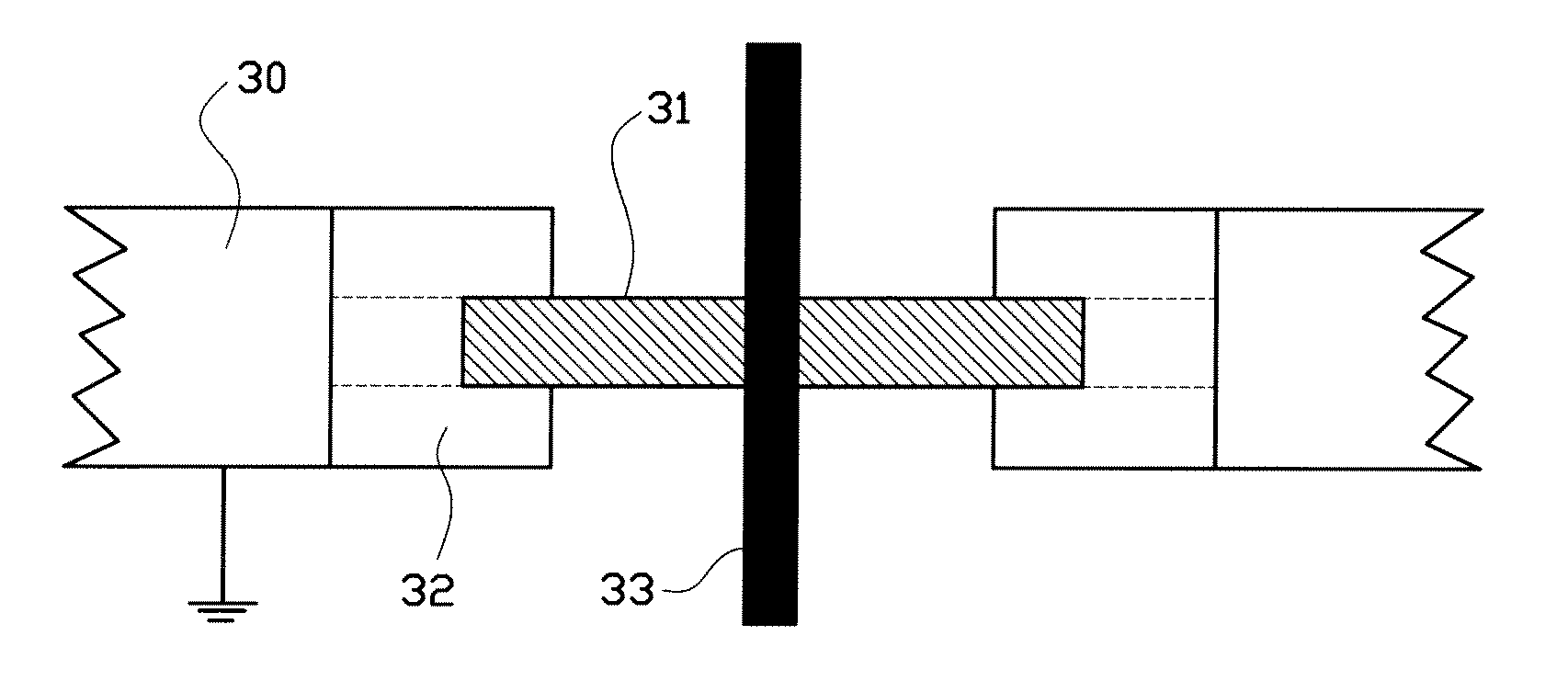
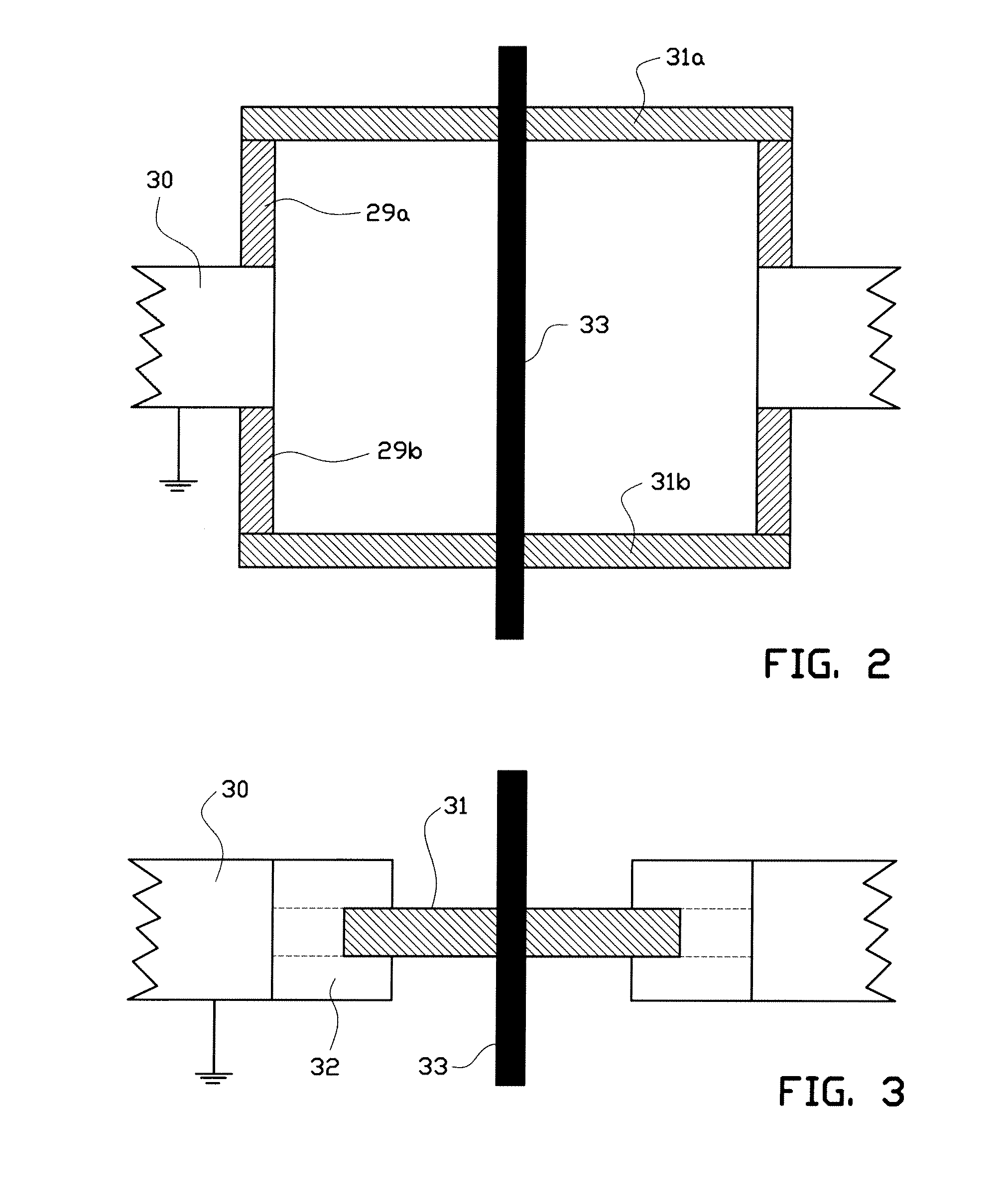
[0017]In providing a technical solution to the issues as described in the preceding, the invention encompasses at least one relatively negatively charged metal part that is at least partially encapsulated by the insulator, thereby preventing both electrical breakdown and electron creep to the positive pole. By encapsulating the metal part at negative potential, the electric field lines are forced into the encapsulating insulator, making both electrical breakdown and electron creep impossible.
[0018]An advantage of this novel design is that is greatly reduces space requirements of the shielding, without necessitating an increased mutual distance surface breakdown path. The principle solution provided here may be advantageously applied at various locations within charged particle type of lithography, however may as well favorably be applied in any high voltage application, i.e. also at other parts thereof than at a projection element. In the latter case, such as at high voltage vacuum feed-through, the feature of the second metal part being substantially thin will not apply. A reduction of space requirements is an advantage in space limited applications or applications where size limitations are not necessarily in place but where voluminous shielding arrangements are nevertheless undesirable. The latter being for instance vacuum vessels, where large openings in the vessel are to be avoided, whereas reduced radial distance is typically encountered in charged particle lens applications.

Problems solved by technology

The known constructive solutions in this respect are specifically disadvantageous in a modern day charged particle lithography environment where very high potential structures are to be applied and where, different from what is known from the well known field of high voltage electric distribution, space is a critical design factor.
By encapsulating the metal part at negative potential, the electric field lines are forced into the encapsulating insulator, making both electrical breakdown and electron creep impossible.

Method used


Image

  • High voltage shielding arrangement
  • High voltage shielding arrangement
  • High voltage shielding arrangement

Examples


Embodiment Construction

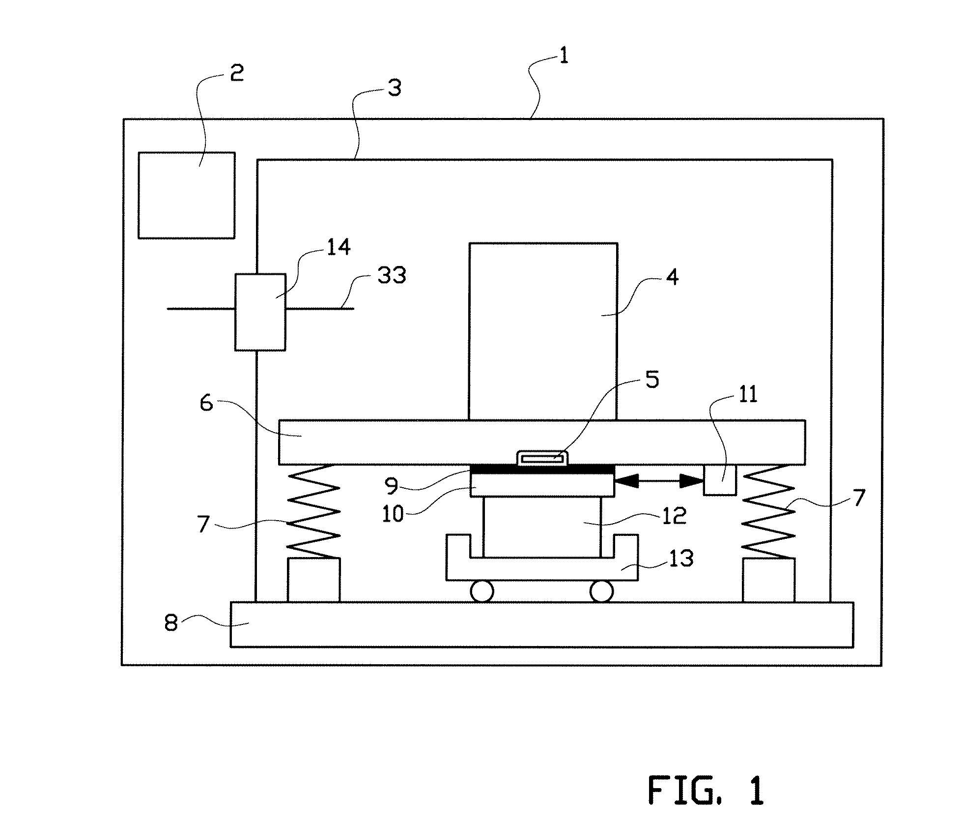
[0028]FIG. 1 is a schematic representation of a prior art charged particle system 1 for projecting an image, in particular a control system provided image, onto a target. It includes the wafer stage components to which part of the present invention relates in particular. In this design the charged particle system comprises a control system 2, a vacuum chamber 3 mounted on the base frame 8, which contains the charged particle column 4, the metro frame 6 and the target positioning system 9-13. Said target 9 will generally be a wafer provided with a charged particle sensitive layer in the substrate plane. Target 9 is placed on top of wafer table 10, which are in turn place on chuck and long stroke drive 13. Measurement system 11 is connected to metrology frame 6 and provides measurements of the relative positioning of wafer table 10 and metro frame 6. The metro frame 6 typically is of relatively high mass and is suspended by vibration isolators 7 for example embodied by spring elements...


PUM


Abstract

The invention relates to a high voltage shielding arrangement comprising a first metal part and a second metal part positioned in close vicinity to said first metal part. Said second metal part included in said arrangement to be set at an electrical potential that is lower than the electric potential of the first metal part. Said second metal part having comprising one or more edges and an insulator. The second metal part is at least partially encapsulated by the insulator facing the first metal part.

Description

BACKGROUND[0001]1. Field of the Invention[0002]The present invention relates to a high voltage shielding design as defined by the preamble of claim 1, and particularly originates from a desire and requirement to apply known high voltage technology in a modern charged particle lithography system.[0003]Such shielding designs are generally encountered in the art of high voltage engineering. In known constructions this is often realized by placing positive and negative poles of an electrical circuit at a certain and fairly large distance apart to prevent electrical breakdown. In other solutions the electric discharge path is elongated, e.g. by providing undulations and other kind of irregularities in said path.[0004]Both known types of solution in practice lead to either or both of a voluminous and an elaborate construction. This is in particular in the technologically highly intensive, and therefore cost and capital intensive environment of lithography highly undesired. It is therefore...

Claims


Application Information

Patent Timeline
IPC IPC(8): H01J1/52
CPCH01J37/02H01J2237/038H01J2237/0203H01J37/317H05K9/00
Inventor KONING, JOHAN JOOSTSTEENBRINK, STIJN WILLEM HERMANBAARS, NORMAN HENDRIKUS RUDOLFSCHIPPER, BART
Owner ASML NETHERLANDS BV
Learn More