
Gasifier comprising vertically successive processing regions

a gasifier and processing region technology, applied in the field of gasification, can solve the problems of insufficiently addressing the problems of prior systems and processes in vertically oriented gasifiers, the inability to achieve significant commercial use of the practicable efficient system, and the rise of the temperature in the gasifier often above the slagging temperatur

Inactive Publication Date: 2011-04-07
PLASCO ENERGY GROUP INC
View PDF29 Cites 15 Cited by
  • Summary
  • Abstract
  • Description
  • Claims
  • Application Information

AI Technical Summary

Benefits of technology

This design improves the overall efficiency of the gasification process by maintaining optimal temperature ranges for each process stage, reducing slag formation, and ensuring consistent operation despite variations in feedstock composition and moisture content.

Problems solved by technology

Numerous converters are known in the art, however, a practical efficient system has not yet achieved significant commercial use.
Most of them have been affected in the volatilization stage by heat transfer problems attendant to the large variance in composition and moisture content of the feedstock.
However, in practise, the temperature in the gasifier often rises above the slagging temperature due to variances in content and moisture of the feedstock.
This results in formation of a tenaciously adhering slag coating comprising of the inorganic components of the waste melt, on all surfaces of the gasifier exposed to the waste.
Prior systems and processes in vertically oriented gasifiers have not adequately addressed the problems that must be dealt with on a continuously changing basis.

Method used


Image

  • Gasifier comprising vertically successive processing regions
  • Gasifier comprising vertically successive processing regions
  • Gasifier comprising vertically successive processing regions

Examples


Embodiment Construction

Definitions

[0055]As used herein, the term ‘about’ refers to a + / −10% variation from the nominal value. It is to be understood that such a variation is always included in any given value provided herein, whether or not it is specifically referred to.

[0056]The terms ‘carbonaceous feedstock’ and ‘feedstock’, as used interchangeably herein, are defined to refer to carbonaceous material that can be used in the gasification process. Examples of suitable feedstock include, but are not limited to, hazardous and non-hazardous waste materials, including municipal wastes; wastes produced by industrial activity; biomedical wastes; carbonaceous material inappropriate for recycling, including non-recyclable plastics; sewage sludge; coal; heavy oils; petroleum coke; heavy refinery residuals; refinery wastes; hydrocarbon contaminated solids; biomass; agricultural wastes; municipal solid waste; hazardous waste and industrial waste. Examples of biomass useful for gasification include, but are not lim...


PUM

PropertyMeasurementUnit
pressuresaaaaaaaaaa
temperatureaaaaaaaaaa
temperaturesaaaaaaaaaa

Abstract

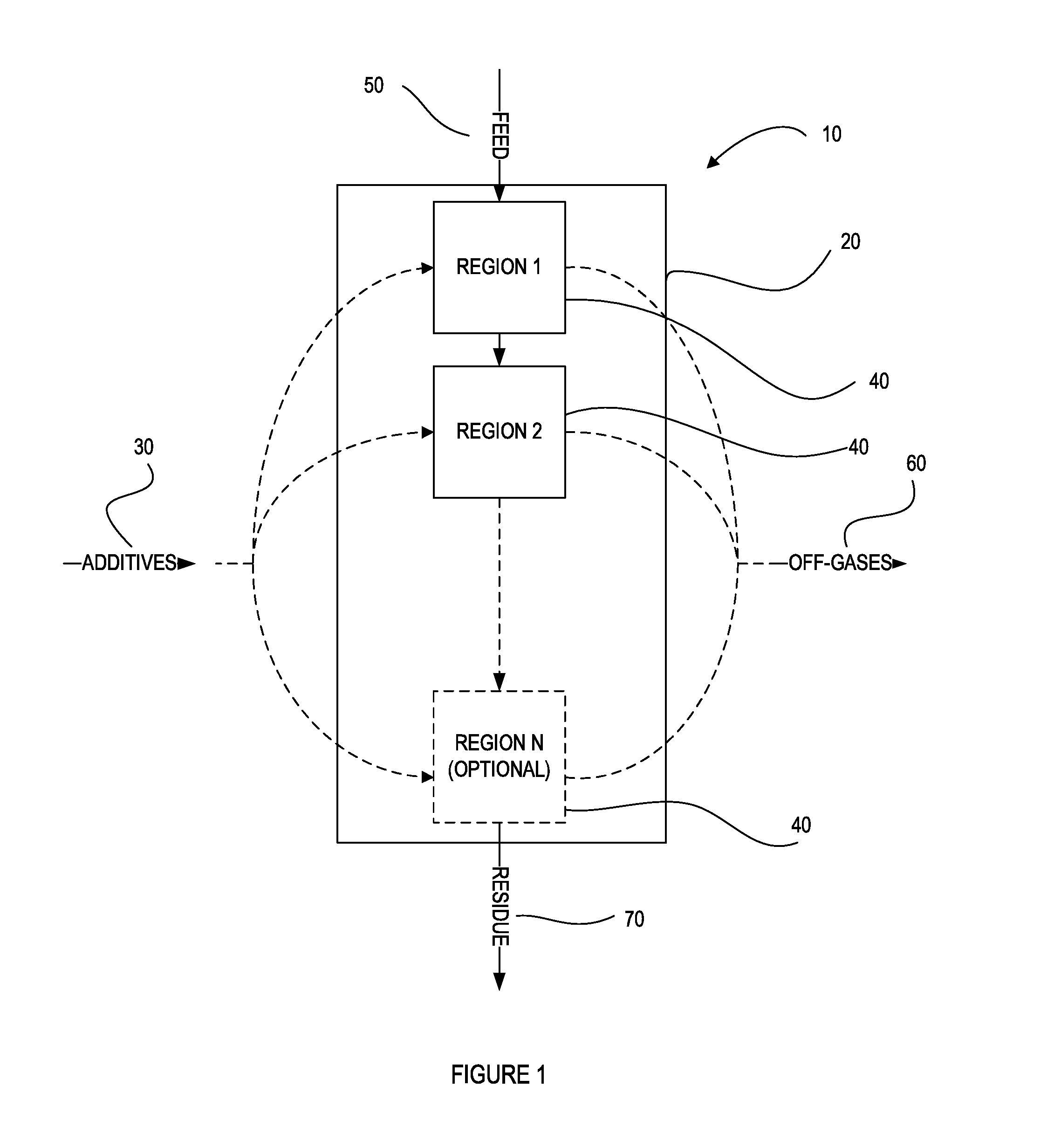
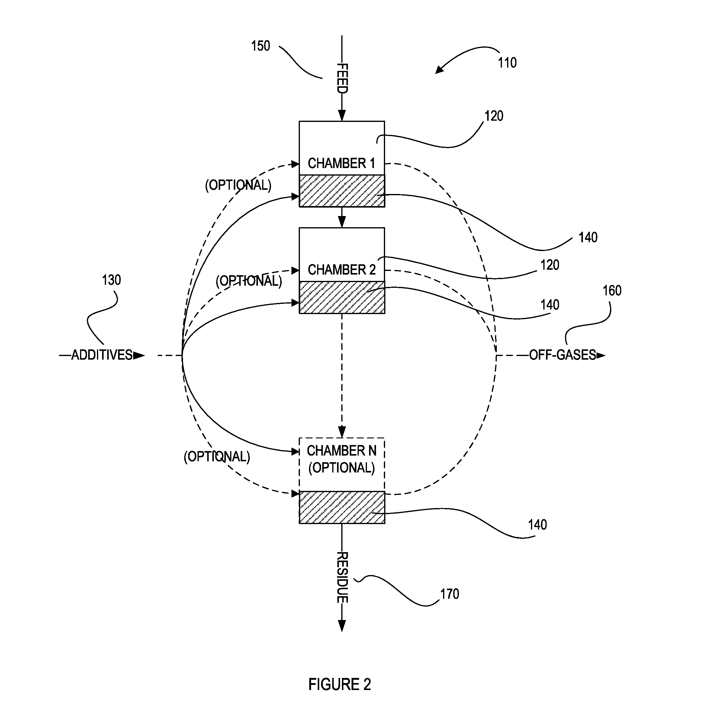
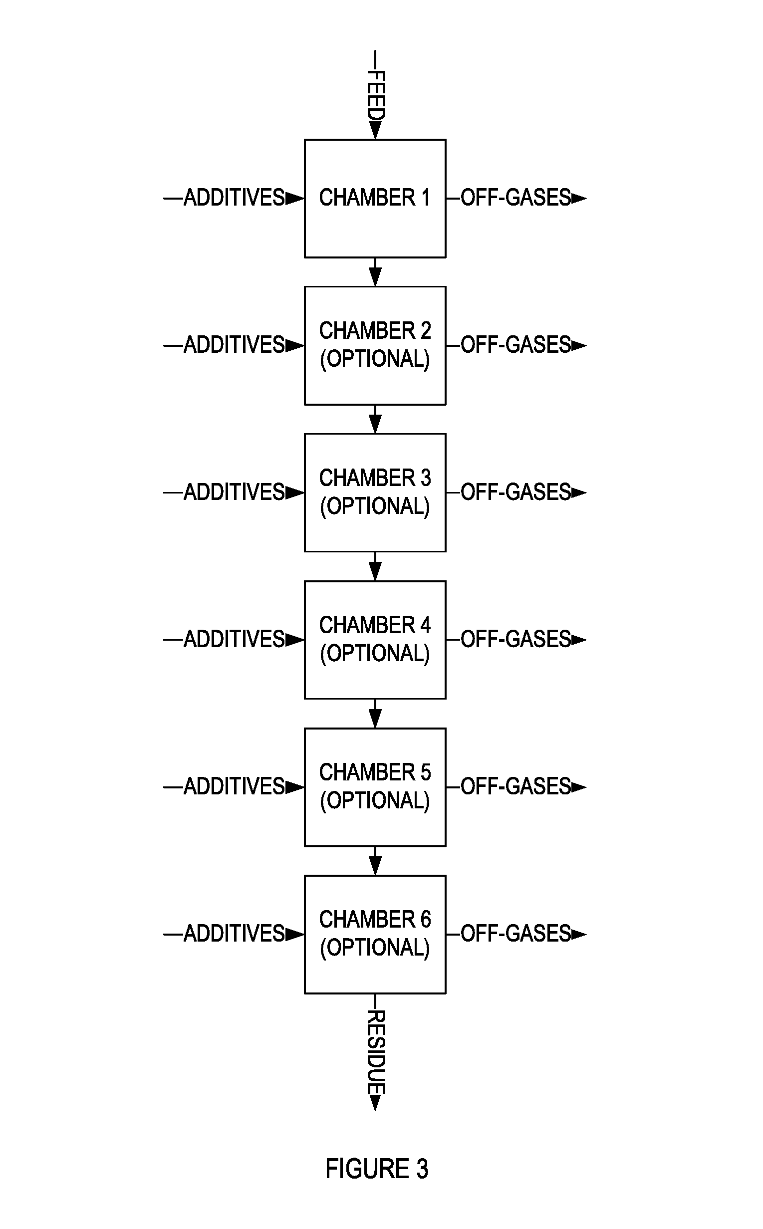
The present invention provides a vertically oriented gasifier comprising vertically successive processing regions for conversion of carbonaceous feedstock into gas. The gasifier comprises of: one or more processing chambers with two or more vertically successive processing regions being distributed within said one or more processing chambers, within each one of which a respective process selected from the group consisting of drying, volatilization and carbon conversion is at least partially favoured. The processing regions are identified by temperature ranges respectively enabling each said respective process. One or more additive input elements are associated with the processing regions for inputting additives to promote each said at least partially favoured process therein. In addition, the gasifier comprises one or more material displacement control modules adapted to control a vertical movement of the feedstock through said processing regions to enhance each said at least partially favoured process, one or more feedstock inputs located near a first of said processing regions and one or more gas outputs and one or more residue outputs.

Description

CROSS REFERENCE TO RELATED APPLICATION[0001]This application is a continuation of U.S. patent application Ser. No. 11 / 758,633, filed 5 Jun. 2007, which is a continuation-in-part and claims benefit of priority to International Patent Application No. PCT / CA2006 / 000881, filed 5 Jun. 2006. The contents of each of these applications is hereby expressly incorporated by reference in their entirety.FIELD OF THE INVENTION[0002]The invention pertains to the field of gasification, and, in particular, to a vertically oriented gasifier for conversion of carbonaceous feedstock into a gas.BACKGROUND[0003]Gasification is a process that enables the conversion of carbonaceous feedstock, such as municipal solid waste (MSW), biomass or coal, into a combustible product gas. The product gas can be used to generate electricity or as a basic raw material to produce chemicals and liquid fuels.[0004]Generally, the gasification reaction consists of feeding carbonaceous feedstock into a heated gasifier along w...

Claims


Application Information

Patent Timeline
Patent Type & Authority Applications(United States)
IPC IPC(8): C10J3/72
CPCC10J3/22Y02E50/14C10J3/482C10J3/523C10J3/723C10J2200/15C10J2300/0916C10J2300/092C10J2300/0923C10J2300/093C10J2300/0946C10J2300/0956C10J2300/0973C10J2300/1238C10J2200/152C10J3/34Y02P20/129Y02E50/10C10J3/66C10J3/20C10B53/02C10L3/08C10B53/07
Inventor TSANGARIS, ANDREASSWAIN, MARGARET
Owner PLASCO ENERGY GROUP INC
Learn More