
Superconducting magnet device for single crystal pulling apparatus

a single crystal, superconducting magnet technology, applied in superconducting magnets/coils, lighting and heating apparatus, magnetic bodies, etc., can solve the problems of requiring a lot of attention for the arrangement of projecting parts such as refrigerators and current lead terminals, and achieve the effect of enhancing workability and safety in working, and suppressing interference with pulling apparatus

Active Publication Date: 2011-03-31
KK TOSHIBA
View PDF5 Cites 3 Cited by
  • Summary
  • Abstract
  • Description
  • Claims
  • Application Information

AI Technical Summary

Benefits of technology

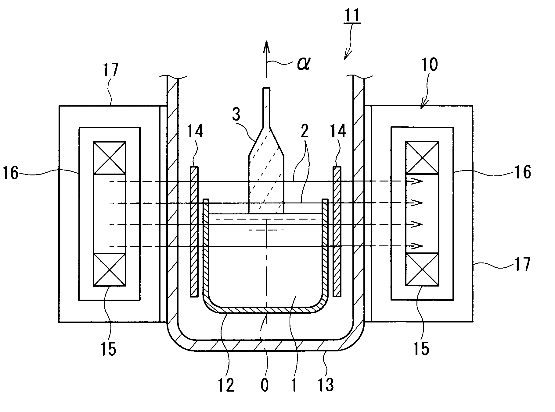
[0009]The present invention has been made in consideration of the circumstances described above, and an object of the present invention is to provide a superconducting magnet device for a single crystal pulling apparatus that can suppress interference with a pulling apparatus and enhance workability and safeness in working of an operator on the apparatus, in addition to securing of a margin for adjusting an applied magnetic field.
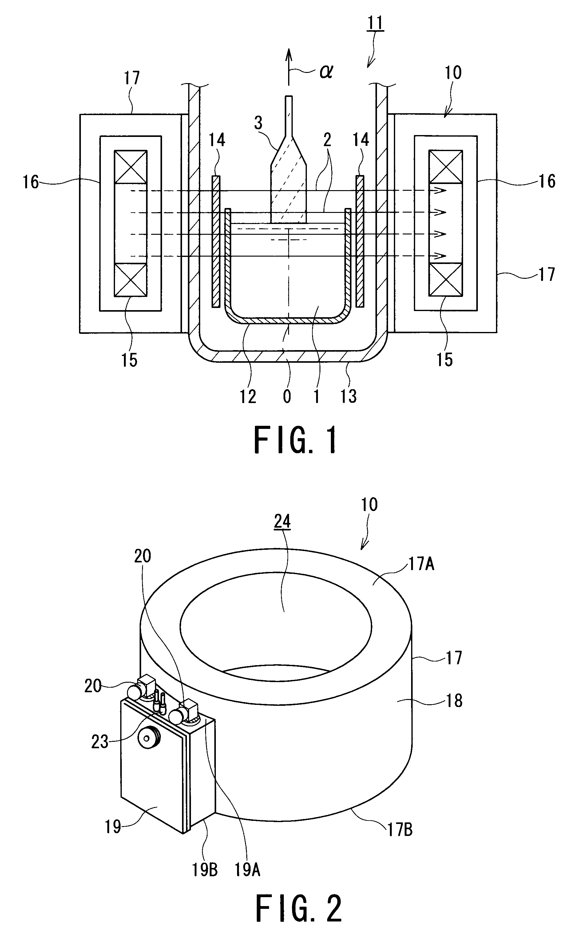
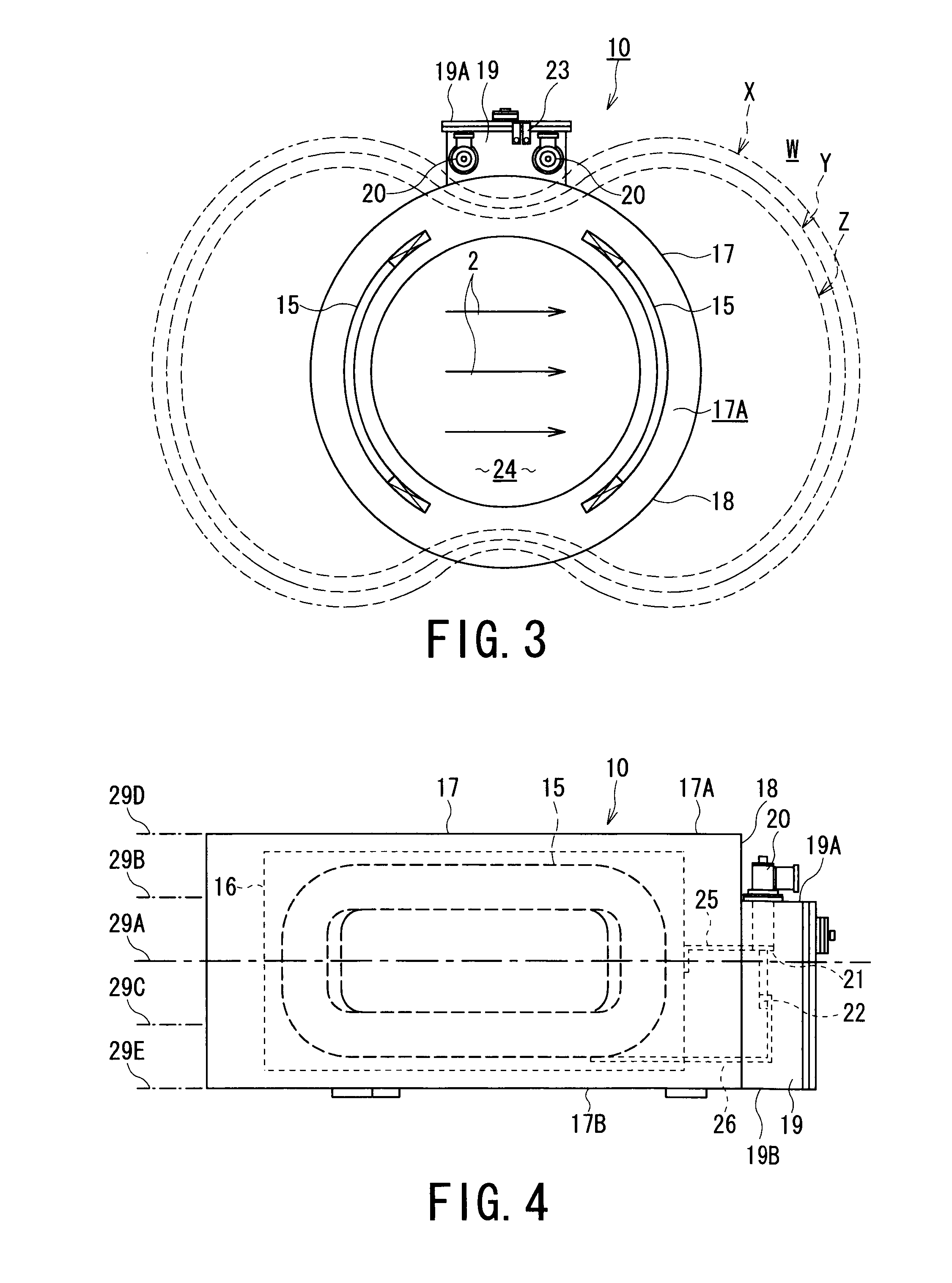
[0018]According to the present invention having the characteristic features mentioned above, since the refrigerator port including a cryogenic refrigerator is arranged on an outer surface of a cryostat, the upper end face of the cryostat is made to be flat. As a result, interference with a pulling apparatus can be suppressed, and workability and safeness in working of an operator on the apparatus can be enhanced. Further, a protruding portion such as a leg portion does not exist on a lower end face of the cryostat, and it is hence possible to set the entire height dimensions of the apparatus to a low level. Accordingly, a margin for adjusting a magnetic field that adjusts an applied magnetic field by raising and lowering the apparatus can be favorably secured.

Problems solved by technology

Further, when taking into consideration the workability and safety of an operator performing operations on the upper end face, the arrangement of projecting parts such as a refrigerator and a current lead terminal requires a lot of attention.

Method used


Image

  • Superconducting magnet device for single crystal pulling apparatus
  • Superconducting magnet device for single crystal pulling apparatus
  • Superconducting magnet device for single crystal pulling apparatus

Examples


third embodiment

[0068]Although a diagrammatic representation of a third embodiment is omitted herein, this embodiment is one in which a plurality of the refrigerator ports shown in FIG. 2 are provided, as shown in FIG. 11.

[0069]A superconducting magnet device for a single crystal pulling apparatus of the present third embodiment differs from the superconducting magnet devices 10 and 30 according to the first and second embodiments in the point that the refrigerator ports on which a plurality of the cryogenic refrigerators 20 are mounted are continuously arranged in an annular shape on the outer circumferential surface 18 of the cryostat 17. More specifically, the third embodiment is one in which a plurality of the refrigerator ports 19 shown in FIG. 2 are arranged on an outer circumferential surface of the cryostat 17 as shown in FIG. 11.

[0070]Accordingly, in addition to advantages similar to advantages (1) to (4) obtained with the first and second embodiments, the following advantage (5) is furthe...


PUM

PropertyMeasurementUnit
cryogenic temperatureaaaaaaaaaa
temperatureaaaaaaaaaa
currentaaaaaaaaaa

Abstract

A superconducting magnet device for a single crystal pulling apparatus is arranged outside a pulling furnace containing a crucible for melting a single crystal material therein so as to apply a magnetic field to the melted single crystal material. The superconducting magnet device for a single crystal pulling apparatus includes a cryostat containing a superconducting coil therein, and a refrigerator port arranged on the outer circumferential surface of the cryostat and provided with a cryogenic refrigerator that cools the superconducting coil. The cryogenic refrigerator is provided in a region of the outer surface region of the cryostat at which the intensity of the magnetic field generated by the superconducting coil is weak.

Description

TECHNICAL FIELD[0001]The present invention relates to a superconducting magnet device for a single crystal pulling apparatus that is used in a single crystal pulling apparatus for producing a single crystal (for example, a semiconductor single crystal).BACKGROUND ART[0002]There is known a single crystal pulling apparatus utilizing an MCZ (magnetic-field-applied Czochralski) method in which a crucible melting a single crystal material (particularly, a semiconductor single crystal material) is contained inside a pulling furnace, and a superconducting magnet device is disposed outside the pulling furnace. A magnetic field is applied to the single crystal material which is melted inside the crucible by the superconducting magnet device to thereby prevent convection of the melted single crystal material.[0003]When producing a silicon single crystal using the MCZ method, in many cases, the shape and size of a super-conducting magnet device for applying a magnetic field is restricted in or...

Claims


Application Information

Patent Timeline
Patent Type & Authority Applications(United States)
IPC IPC(8): H01L39/02H01F6/00
CPCC30B15/305Y10T117/1068H01F6/04
Inventor TAKAMI, SHOHEISHIMONOSONO, TSUTOMUOTA, TOMOKOMINEMOTO, YUUJINAGAMOTO, YOSHIFUMIUSHIJIMA, MAKOTO
Owner KK TOSHIBA
Learn More