
Transmitting a Radio Signal in a Mobile Communication Network

a radio signal and mobile communication technology, applied in the direction of electromagnetic wave modulation, polarised antenna unit combination, modulation, etc., can solve the problems of inability to achieve optimal rx diversity under all circumstances, and inability to achieve diversity optimal performance, etc., to achieve the effect of reducing the sensitivity to cross-polarization fading, improving the reception quality of signals of mobile terminals without diversity

Inactive Publication Date: 2011-03-24
VODAFONE GRP PLC
View PDF3 Cites 2 Cited by
  • Summary
  • Abstract
  • Description
  • Claims
  • Application Information

AI Technical Summary

Benefits of technology

[0012]As a result thereof, the signal reception quality of mobile terminals not employing diversity reception is improved with the circular polarisation achieved because of decreased sensitivity to cross-polarization fading. Indeed the received signal quality varies much less as now misalignment between the mobile terminal antenna and the received polarisation is prevented. As a result, there are fewer occasions in which the received signal quality is bad than with a linearly polarised radio signal transmitted by the radio access node.
[0013]Furthermore, the antenna of a mobile terminal with diversity reception in good radio conditions now receives a similar energy level in both antenna elements resulting in optimum diversity performance. It can be theoretically demonstrated that the signal level received in both branches is not dependent on the incident angle between the propagation direction of the radio signal and the plane of the orthogonal antenna elements.
[0014]As a result, the received signal fading in both mobile terminals without diversity reception and mobile terminals with diversity reception is reduced.
[0015]The diversity gain obtained with the present invention has a significant effect in mobile communication networks using “aggressive” signal modulation, such as 16QAM used in High-Speed Packet Access (HSPA) or 64QAM used in HSPA+. For example, in UMTS the HSPA throughput is tightly linked to the radio signal quality level. As a result of the reduction of the fading achieved with the present invention, the throughput of HSPA is enhanced, significantly.
[0025]According to a third embodiment, the power divider and phase shift means is integrated in the antenna arrangement. In this case the potential problems that might occur due to differences in feeder lengths are avoided.

Problems solved by technology

However, in case of misalignment at the mobile terminal and / or a strong decoupling between polarisations of the transmitted wave received by the mobile (as an outcome of the propagation of the radio mobile channel) and the polarisation of the mobile antenna system, the quality of the received signal may deteriorate significantly.
Although the received signal quality of such mobile terminals is superior to that of the mobile terminals without diversity reception, the performance of Rx diversity implemented in such a way is not optimal under all circumstances.
Indeed the decoupling of the polarisation of the radio channel is often not strong enough to maximise the overall power received at both reception branches and therefore diversity is usually underperforming on average (long term fading), because the majority of the received signal is captured mainly through one of the reception branches in the antenna mobile station.

Method used


Image

  • Transmitting a Radio Signal in a Mobile Communication Network
  • Transmitting a Radio Signal in a Mobile Communication Network
  • Transmitting a Radio Signal in a Mobile Communication Network

Examples


first embodiment

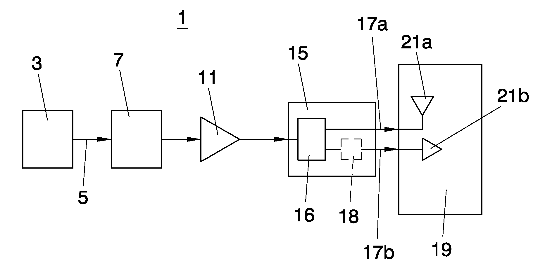
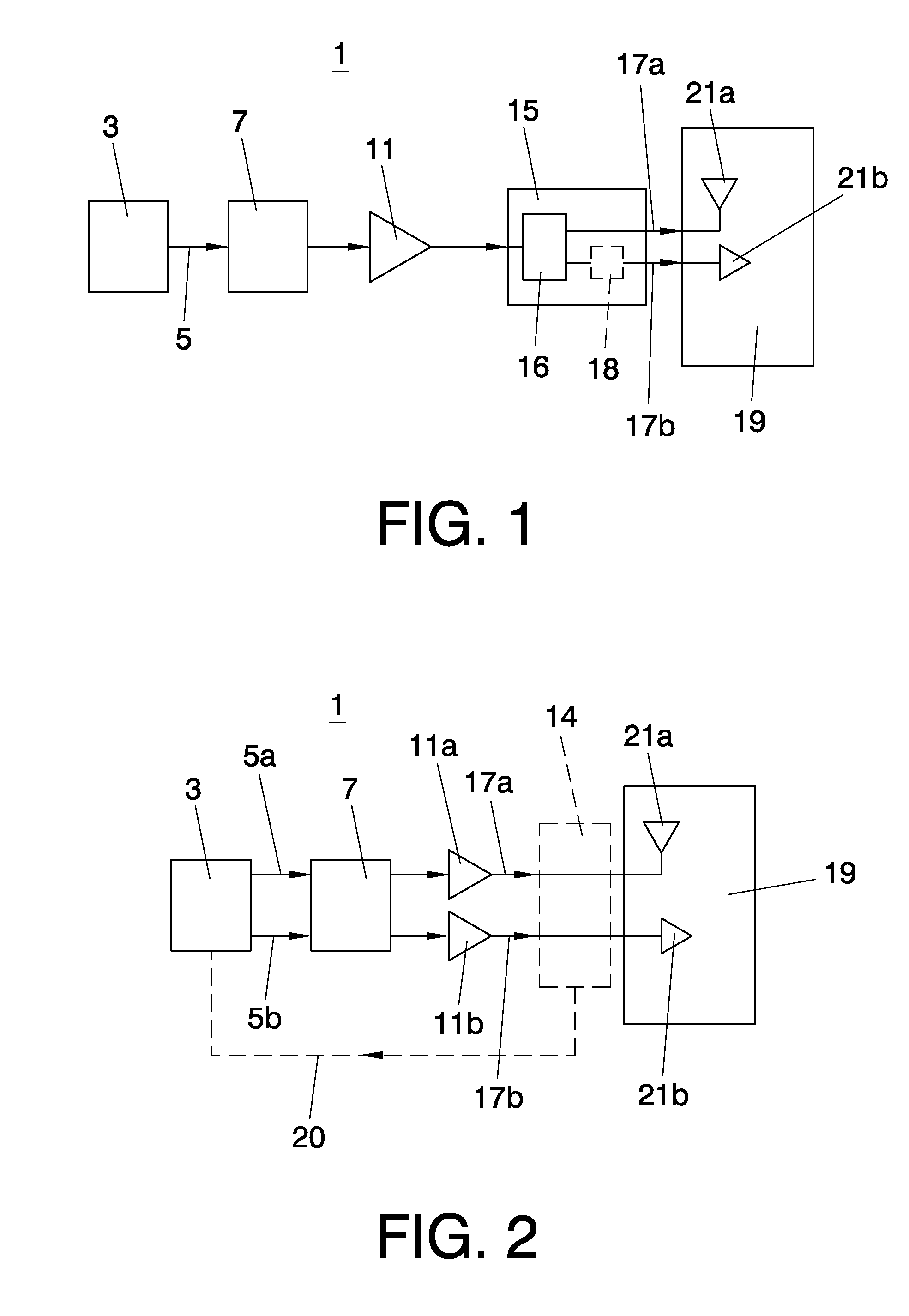
[0037] the transmission means 1 comprise base band processing means 3 providing a base band signal 5. The base band signal 5 is up-converted to a radio frequency by frequency conversion means 7 and amplified by power amplifier 11, thereby obtaining radio signal 13. Radio signal 13 is split by power divider and phase shifting means 15 into the first version of the radio signal 17a and the second version of the radio signal 17b. The power divider and phase shifting means 15 may consist of any passive or active component or combinations of passive or active components that splits an input signal equally between both outputs but with a phase shift of 90 degrees between both output branches. However, the power divider and phase shift means preferably comprises a 90° hybrid combiner 16. This commercially available component comprises two inputs and two outputs and splits the input signal at each input between both outputs with a phase shift of 90 degrees between the output branches. This ...

second embodiment

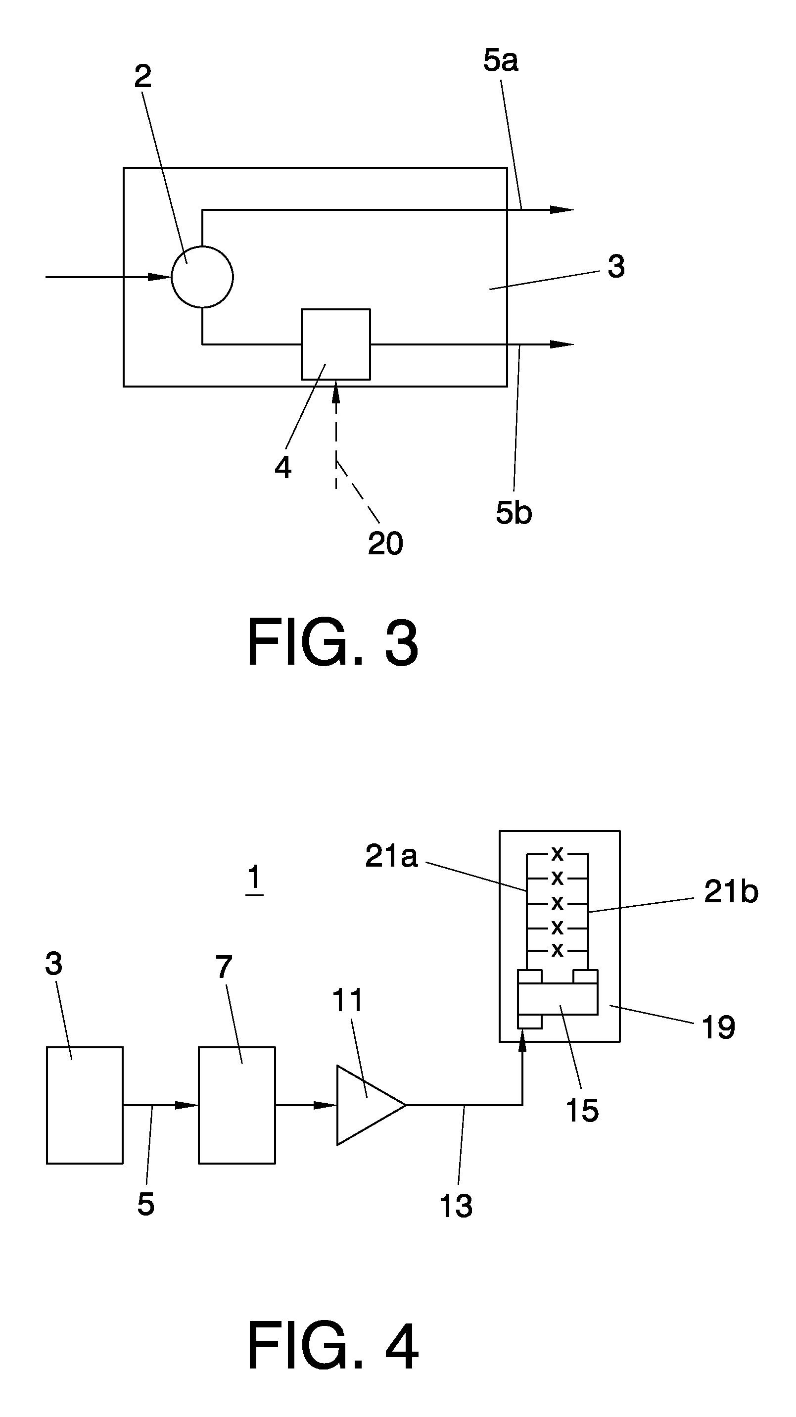
[0040] the signal is already split at base band level by the base band processing means 3, into a first version of the base band signal 5a and a second version of the base band signal 5b. The first version of the base band signal 5a and the second version of the base band signal component 5b contain the same information, have 90° phase difference between them and have equal power. This is shown in more detail in FIG. 3. The base band processing means 3 comprises a base band signal divider 2 for dividing the input signal and a 90° phase shifter 4 for generating the required 90° phase difference. Alternatively, the phase shifter 4 is a variable phase shifter. In this case, a phase shift detector 14 is needed that detects the phase shift between the first version and the second version of the radio signal and provides the variable phase shifter with phase correction information 20, i.e. the deviation of the detected phase shift from 90°. The variable phase shifter is configured to adap...

third embodiment

[0043] shown in FIG. 3, the power divider and phase shift means 15 is inserted in the body of an existing cross polar antenna arrangement 19, wherein the first antenna element 21a and the second antenna element 21b are antenna arrays. In this case, there are no constraints regarding the feeder length between the power divider and phase shift means outputs and the antenna ports inputs because the power divider and phase shift means outputs are directly connected to the antenna elements feeder network.

[0044]The use of the system according to the present invention has proven to be very advantageous for High Speed Downlink Packet Access (HSDPA) bearers. The improvement in the received signal quality of the HSDPA bearer at a HSPA mobile terminal results in a better channel estimation. So, Block Error Rate (BLER) values are lower and the average value of the Channel Quality Indicator (CQI) reported by the mobile terminal increases.

[0045]This is illustrated in FIG. 5, which shows the distr...


PUM


Abstract

System and method for transmitting a radio signal in a mobile communication network. The radio signal has a circular polarisation.

Description

BACKGROUND OF THE INVENTION[0001]1. Technical Field[0002]The present invention relates to a system for transmission of a radio signal in a mobile communication network as well as to a corresponding method.[0003]2. Description of Related Art[0004]In traditional mobile communication networks a carrier signal being generated at base band level in a radio access node is amplified by a power amplifier and radiated over the air with linear polarisation, typically vertical or at + / −45° slant using a single Tx port.[0005]The polarisation properties of the signal transmitted in the radio channel are modified by reflections from and refraction on multiples obstacles before arriving at the receiver of the mobile terminal, causing the power originally transmitted with a given linear polarisation to be progressively rotated and also to progressively decouple into the orthogonal polarisation (e.g. in to the horizontal if the transmitted wave was at vertical polarisation)[0006]Most mobile terminal...

Claims


Application Information

Patent Timeline
Patent Type & Authority Applications(United States)
IPC IPC(8): H04B1/02H04B1/04H01Q11/12
CPCH01Q21/24H04B2001/045H04B1/0475H01Q21/26H03F1/02H03F3/24H04B1/04
Inventor DE PASQUALE, ANDREAEXADAKTYLOS, KYRIAKOSALCAZAR VIGUERA, ESPERANZADIAZ MATEOS, MARIAGARRIGA MUNIZ, BEATRIZDOMINGUEZ ROMERO, FRANCISCO JAVIERMCWILLIAMS, BRENDANURBANO RUIZ, JULIOSERRANO SOLSONA, CLARALOPEZ ROMAN, JAVIERGARCIA VINAS, AITORTENORIO SANZ, SANTIAGOLE PEZENNEC, YANNICK
Owner VODAFONE GRP PLC
Learn More