Method for cleaning containers and cleaning machine

a container and cleaning machine technology, applied in the direction of cleaning hollow objects, manufacturing tools, liquid cleaning, etc., can solve the problems of enormous cost of cleaning containers, large amount of water and chemicals per container to be cleaned, and large amount of energy for generating heat, so as to achieve easy biodegradability and easy recycling

Inactive Publication Date: 2011-03-24
KRONES AG
View PDF7 Cites 19 Cited by
  • Summary
  • Abstract
  • Description
  • Claims
  • Application Information

AI Technical Summary

Benefits of technology

[0031]The quintessence of the disclosure is to employ essentially no chemicals or no chemicals at all in the container cleaning process in a cleaning machine, but to work with chemical-free cleaning media which do not develop their cleaning effect in a chemical, but in another manner, e.g. physically and/or mechanically. This can be e.g. granular material having an abrasive effect when being blasted under pressure. The granular material releases dirt accumulations, carries away the released dirt accumulations and can be removed again without leaving any residue. If the granular material is ice, a cold shock effect which intensifies cleaning is added to the abrasive cleaning effect. All procedure steps can be performed essentially without heat or with the addition of only little heat to finally achieve a cleaning result which is at least as good as it was possible up to now only with the addition of a lot of water, chemicals and thermal energy. When working with granular material inside the container, the granular material is injected under pressure until a certain filling level is reached. During...

Problems solved by technology

These well-known methods require a considerable amount of water and chemicals per container to be cleaned as well as a considerable amount of energy for generating heat.
The high amount of water required is, among others, due to the chemicals not only having to be employed in a certain dilution for cleaning, but also having to be removed without leaving any residue.
T...

Method used


Image

  • Method for cleaning containers and cleaning machine
  • Method for cleaning containers and cleaning machine
  • Method for cleaning containers and cleaning machine

Examples


Embodiment Construction

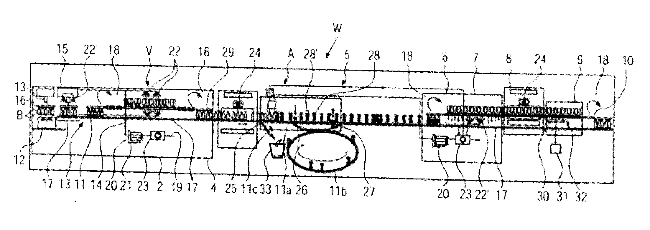
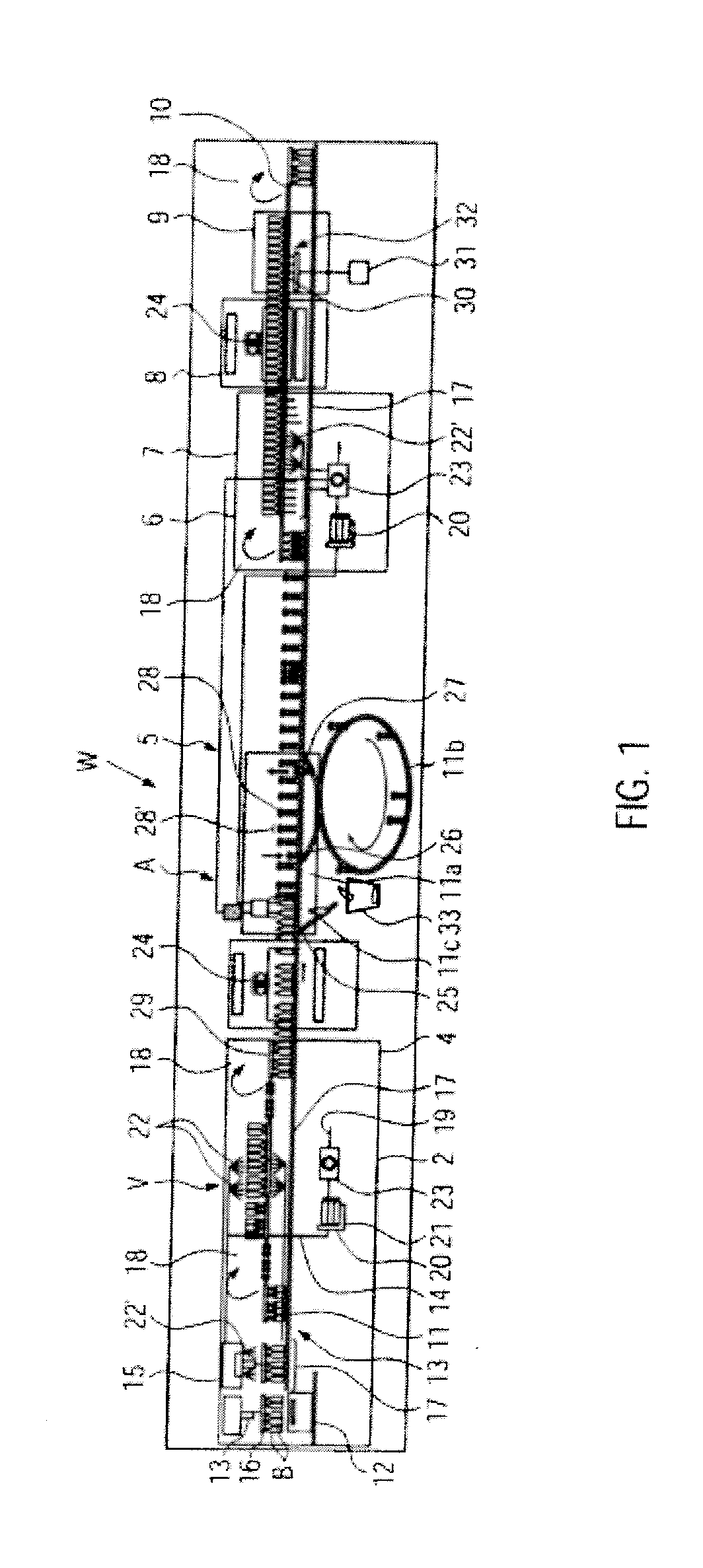
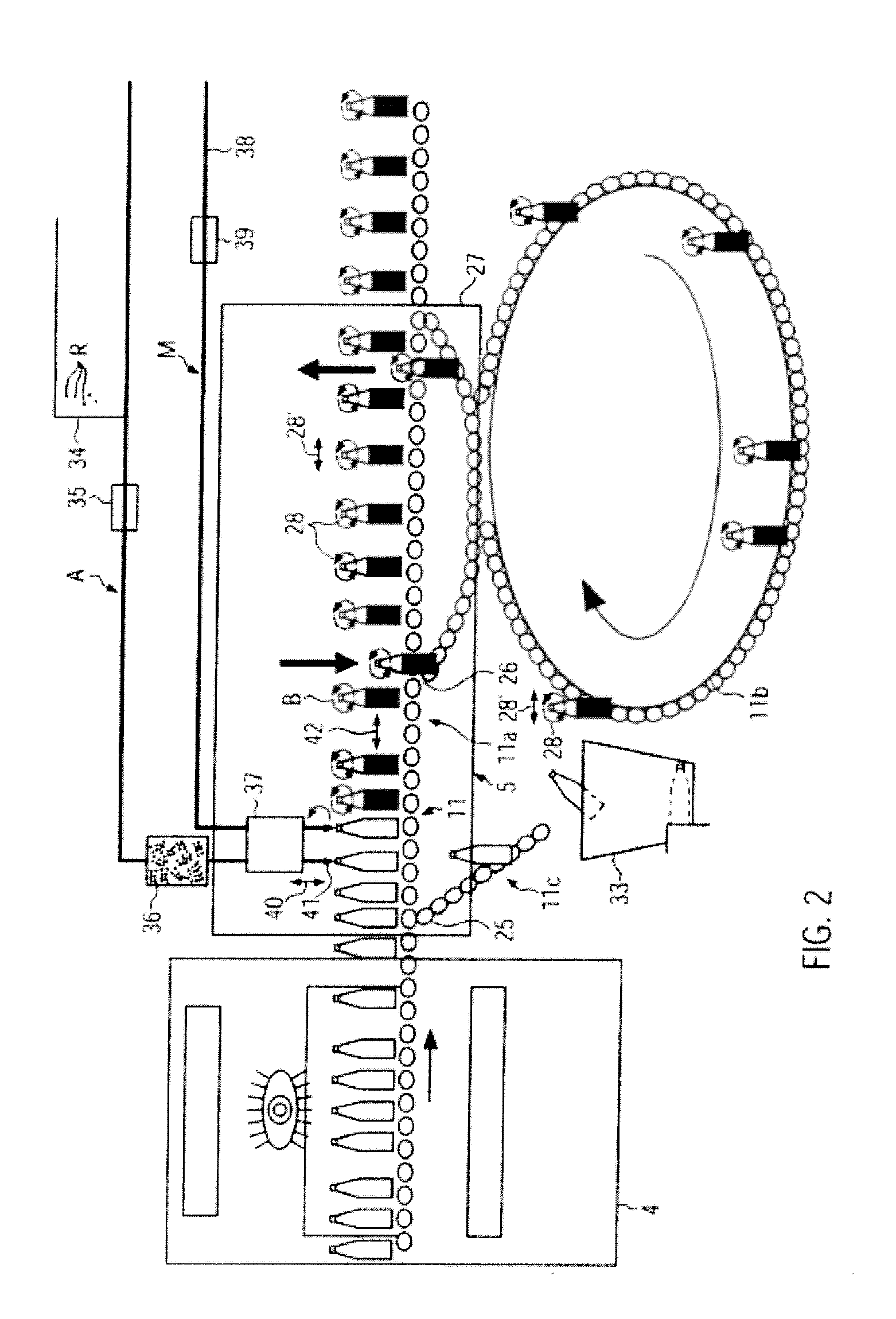
[0037]A cleaning machine W shown in FIGS. 1 and 2 serves, for example, for cleaning containers B which are at least predominantly returned by consumers and refilled according to a multi-cycle principle. These can especially be plastic or glass bottles for the beverage industry for which very high cleaning and hygienic standards must be kept for refilling.

[0038]The cleaning machine W shown in FIGS. 1 and 2 is designed as linear machine, but alternatively, it could also be a rotary machine.

[0039]In the cleaning machine W, several stations 1 to 10 are connected in series in the conveying direction of the containers B. A conveyor line 11 for upright transport extends through all stations, auxiliary conveyor lines 29 for example for suspended transport or overhead transport being associated to them in parallel.

[0040]Station 1 is an unpacking and presoaking station. The containers B are lifted for example out of transport units 12 by means of a gripper 13, 16 and placed onto the conveyor ...


PUM

PropertyMeasurementUnit
Timeaaaaaaaaaa
Lengthaaaaaaaaaa
Pressureaaaaaaaaaa

Abstract

A method for cleaning containers, in particular bottles of glass or plastics, and a cleaning machine with at least one cleaning medium, with the containers cleaned at least in one station preferential for the cleaning result and/or in a procedure step with at least essentially chemical-free cleaning media. The cleaning medium is advantageously a granular material, in particular granular ice, carried under pressure with compressed air or compressed water. The cleaning machine suited for carrying out the method includes downstream of an unpacking and presoaking station, a pre-cleaning station with a high pressure water blasting pre-cleaning section, and subsequently an intensive cleaning station with at least one intensive cleaning section to which a pressure blasting system for chemical-free, granular material and a carrier medium are associated, and a disinfection station following the intensive cleaning station.

Description

CROSS-REFERENCE TO RELATED APPLICATION[0001]The present application claims the benefit of priority of German Application No. 102009039762.0, filed Sep. 2, 2009. The entire text of the priority application is incorporated herein by reference in its entirety.FIELD OF THE DISCLOSURE[0002]The disclosure relates to a method and a cleaning machine for cleaning containers, such as in beverage bottling operations.BACKGROUND[0003]It is known, for example in the beverage industry to employ a considerable amount of chemicals, such as caustic solutions or acids, directly at or in the containers and possibly also work with heat for cleaning containers, in particular bottles of plastics or glass, in connection with water. These well-known methods require a considerable amount of water and chemicals per container to be cleaned as well as a considerable amount of energy for generating heat. The high amount of water required is, among others, due to the chemicals not only having to be employed in a ...

Claims


Application Information

Patent Timeline
IPC IPC(8): B08B9/00
CPCB08B9/38B08B2203/005B08B9/46
Inventor FOLZ, CORNELIAMOMSEN, JANHUMELE, HEINZKIRCHHOFF, TIMMWASMUHT, KLAUS-KARLHANSEN, BERNDISLINGER, THOMASWEINHOLZER, CHRISTOPH
Owner KRONES AG
Why Eureka
Try Eureka