Eureka AIR delivers breakthrough ideas for toughest innovation challenges, trusted by R&D personnel around the world.

Vehicular fluid heater

a heater and fluid technology, applied in vehicle cleaning, household stoves or ranges, lighting and heating apparatus, etc., can solve the problems of affecting the efficiency of heating, and difficult to implement leak-proof functions, so as to achieve effective and efficient heat transfer, improve efficiency and benefits

Inactive Publication Date: 2011-03-17
WU CHIA HSIUNG
View PDF12 Cites 23 Cited by
  • Summary
  • Abstract
  • Description
  • Claims
  • Application Information

AI Technical Summary

Benefits of technology

[0009]The present invention is to provide a vehicular fluid heater to improve effectiveness and benefits of a vehicular fluid heating system. The primary objective of the present invention is to use a laminated heating composite flatly joined to a heat conduction surface of a heat exchange vessel, and to utilize electrical and thermal functions of the aforementioned fluid heating system to effectively and efficiently transfer heat generated by the heating composite to the fluid via material surfaces of the heat exchange vessel, and to enable easy replacement of parts or repairing of the laminated heating composite, and allow assembling one or a plurality of laminated heating composites onto the heat exchange vessel, thereby facilitating a selection of the required power or producing the heating systems.
[0012]A fourth objective of the present invention is to electrically connect a negative plate electrode of the laminated heating composite to the heat exchange vessel directly, with the heat exchange vessel conducting electrically to a negative electrode of a car body, to avoid an electric arc caused by a surge charge originating from a positive plate electrode.
[0013]A fifth objective of the present invention is to assemble the laminated heating composite and the heat exchange vessel, by gluing between them to stop leakage.
[0014]A sixth objective of the present invention is to use a ceramic or polymer resistance heating strip with a positive temperature coefficient (PTC) as a heat source to provide a self-regulated heating characteristic. The use of ceramic material can facilitate reinforcing mechanical strength of the heater system assembly.

Problems solved by technology

However, the heating wire will be fractured along with the packaging material due to external force.
However, as channels are connected serially or parallel, it is more difficult to implement a leak-proof function.
As its structure is formed by abutting and joining a plurality of radiators, gaps will be formed at interfaces, and as paths of thermal compensation between the radiators are cut off, it is not easy to compensate the heat between the radiators.
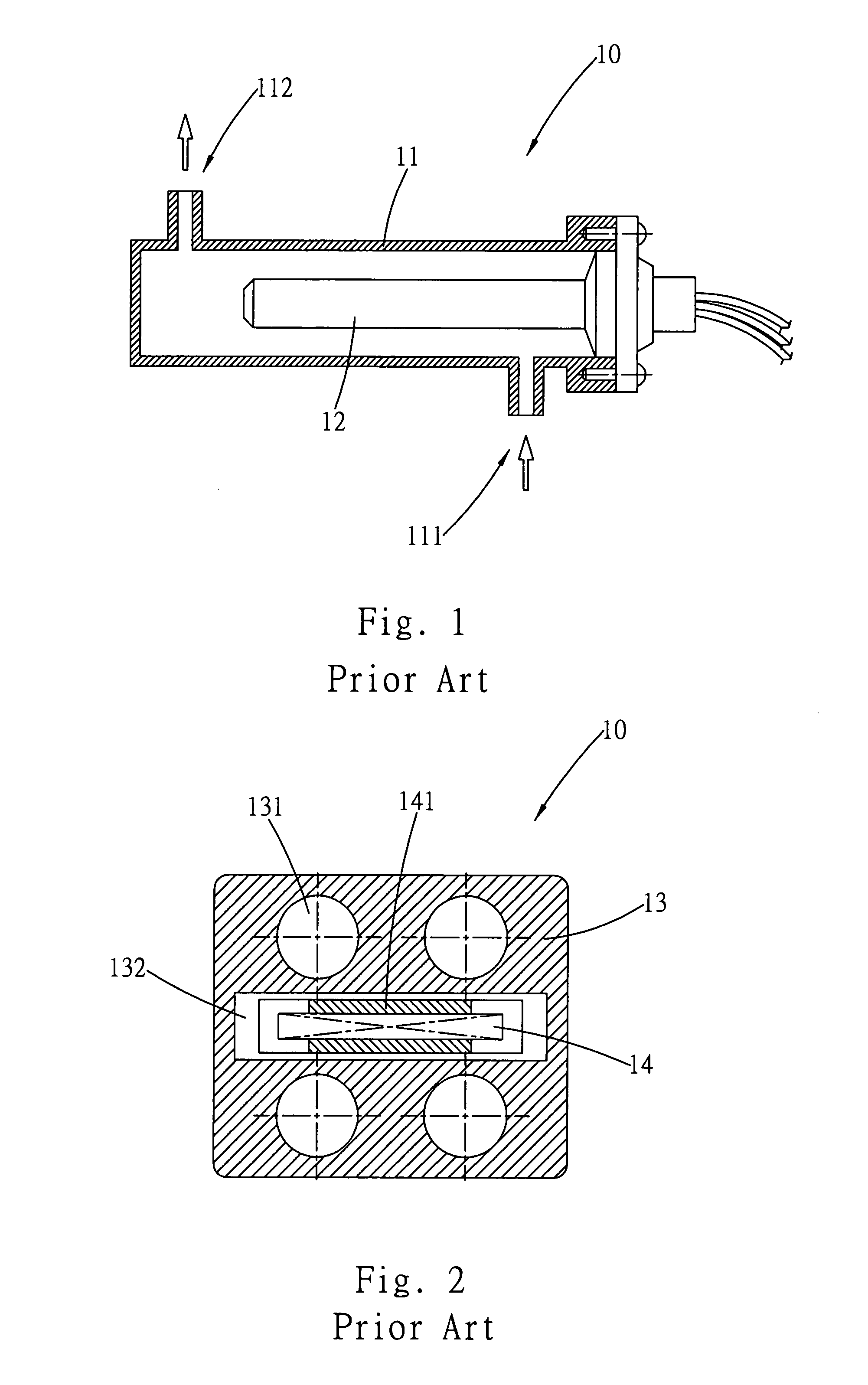
Disadvantages of this type of heating system include high susceptibility to damages due to thermal stress and no means for repairing the damaged heating element 14.
If the heating element 14 fails to function, the entire heating system must be replaced, thereby resulting in excessive waste and adding a burden to ecology.
The aforementioned heating systems of the prior arts are unable to provide different power ratings flexibly, forcing manufacturers to stock heating systems with different power specifications in order to provide rapid responses to customer needs.
This will increase inventory cost of the manufacturer.
Furthermore, these heating system designs of the prior arts prevent standardization for mass production and therefore can increase production cost.

Method used


Image

  • Vehicular fluid heater
  • Vehicular fluid heater
  • Vehicular fluid heater

Examples


Embodiment Construction

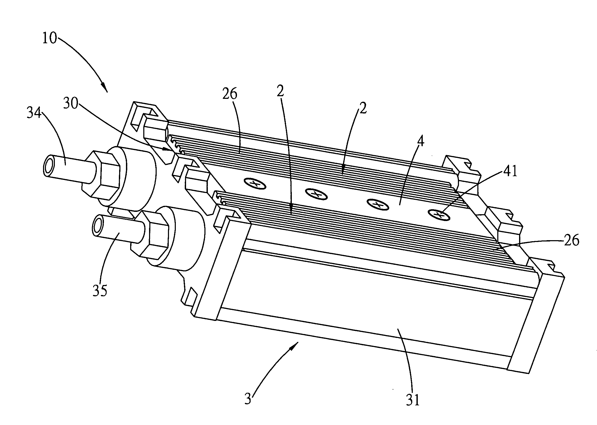
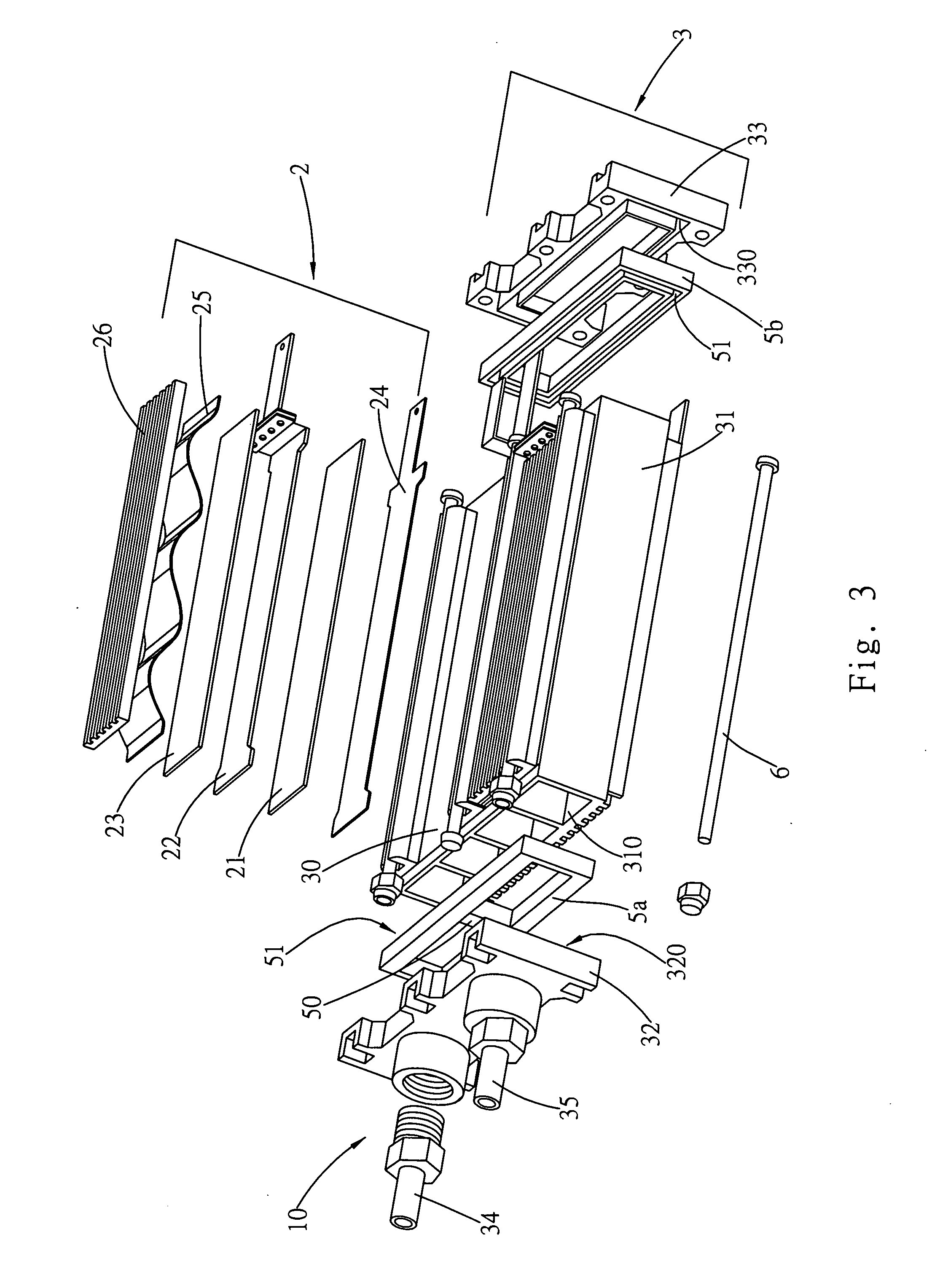
[0029]FIG. 3 shows a schematic view of a heating system 10 which is a heat exchanger 3 comprising a laminated heating composite 2 flatly jointed to a heat exchange vessel 31 of the heat exchanger 3. The laminated heating composite 2 conducts electricity to a heating strip 21 using plate electrodes 22 and 24. An external power switching mechanism can be utilized to control a power-on period for the heater strip 21. As the power switching mechanism is an ordinary manual or automatic switch, it will not be described further.

[0030]An insulating plate 23 with either a good or poor thermal conductivity, depending on specific applications, is used to provide electrical insulation for the laminated heating composite 2. The insulating plate 23 is positioned at an exterior side of the plate electrode 22 and an interior side of a sealing back plate 26.

[0031]The heating strip 21 can be fabricated from any single plate unit of electro-thermal materials such as an electric heating wire or a compo...


PUM


Abstract

A vehicular fluid heater is used to heat fluid for defrosting or cleaning a windshield, a head lamp, etc., and viscous fluid such as hydraulic oil, lubrication oil, etc. to reduce viscosity and improve performance, particularly during a cold condition. The heater is constructed by a plurality of laminated heating composites joined to heat conduction surfaces of a heat exchange vessel, which facilitates ease of production, maintenance, and heating power selection. A fluid field is defined by fluid pathways formed by a structural design that assembles the heat exchange vessel, and a front and a back seal panels disposed on the heat exchanger.

Description

BACKGROUND OF THE INVENTION[0001]a) Field of the Invention[0002]The present invention relates to a vehicular fluid heater, and more particularly a vehicular fluid heater used to heat such as wash fluid for defrosting or cleaning a windshield, a head lamp, or a visual port, or in heat dissolution function of viscous fluid such as diesel fuel, hydraulic oil, lubrication oil, etc. to reduce viscosity or preheat oil molecules for activation, thereby improving performance of an engine, particularly during a cold condition.[0003]b) Description of the Prior Art[0004]In a geographical zone with low or subfreezing temperature during a winter season, viscosity of fluid in a vehicle can decrease its primary functions, whether the fluid is burning fuel, lubrication oil for lubricating parts, or wash fluid for cleaning a windshield. Generally, a fluid heating system will be installed in line with a fluid reservoir to improve the fluid characteristics in a cold weather, such as that an engine can...

Claims


Application Information

Patent Timeline
IPC IPC(8): B60L1/00F24C11/00
CPCB60L2240/36F28F2270/00F24H1/009F24H1/121F24H9/1818F24H9/1827F28D2021/0098F28F1/022F28F3/048F28F9/0253F28F2275/205H05B3/262H05B2203/023F28F2255/14F28F2230/00B60S1/488
Inventor WU, CHIA-HSIUNG
Owner WU CHIA HSIUNG
Why Eureka
Eureka Blog
Learn More