Apparatus for determining the element occupancy on a surface by means of fluorescence

a technology of element occupancy and apparatus, applied in the direction of fluorescence/phosphorescence, measurement devices, instruments, etc., can solve the problems of glass corrosion, adversely affecting the transparency of the surface, and therefore the impression of quality, defects or deficient qualities of coatings or finishings on the gel layer or corroded layer, etc., to achieve the effect of rapid detection of fluorescent regions on the surfa

Inactive Publication Date: 2011-03-10
BOHLE
View PDF8 Cites 7 Cited by
  • Summary
  • Abstract
  • Description
  • Claims
  • Application Information

AI Technical Summary

Benefits of technology

[0012]Starting from this, it is an aspect of the invention to provide an apparatus of the type specified in the Field of the Invention, which makes it possible to achieve a rapid, reliable determination of the element occupancy of a surface and is at the same time easy to operate. Furthermore, the apparatus should be characterized by comparatively low purchase and operating costs and the components used should have a long lifetime.

Problems solved by technology

However, there is some slight diffusion-induced absorption of Sn2+ ions in the surface of the float glass on the tin bath side which constitutes a problem when a particular surface purity is required.
A further appreciable problem is so-called glass corrosion which occurs both on the tin bath side and also on the side facing away from the bath.
A gel layer is formed which further reacts with ions of the acting substance to form an opaque coating which also noticeably adversely affects the transparency of the surface and therefore the impression of quality.
Another problem of glass corrosion is that it can lead to defects or deficient qualities in coatings or finishings on the gel layer or corroded layer.
However, this involves an extremely coarse and inaccurate measurement method since the fluorescence intensity is very low relative to the intensity of the Hg lamp and is strongly superposed by this.
Thus, this comprises an apparatus which can only be handled with difficulty, which additionally does not yield any quantifiable fluorescence measurement result but merely makes the effect of the fluorescence visible on the glass surface.

Method used


Image

  • Apparatus for determining the element occupancy on a surface by means of fluorescence
  • Apparatus for determining the element occupancy on a surface by means of fluorescence
  • Apparatus for determining the element occupancy on a surface by means of fluorescence

Examples


Embodiment Construction

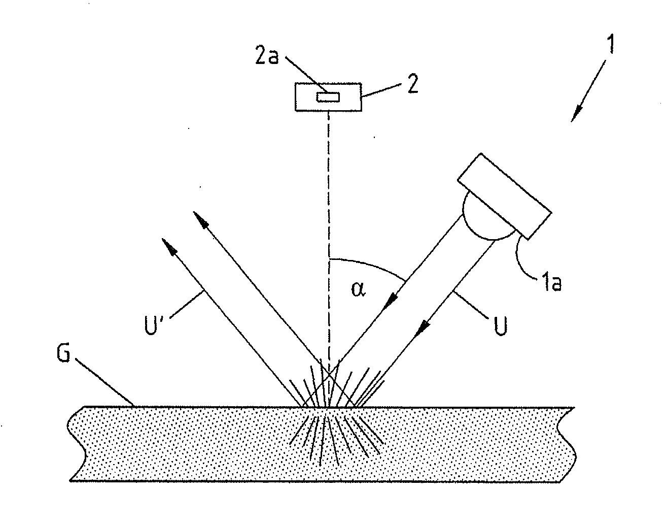
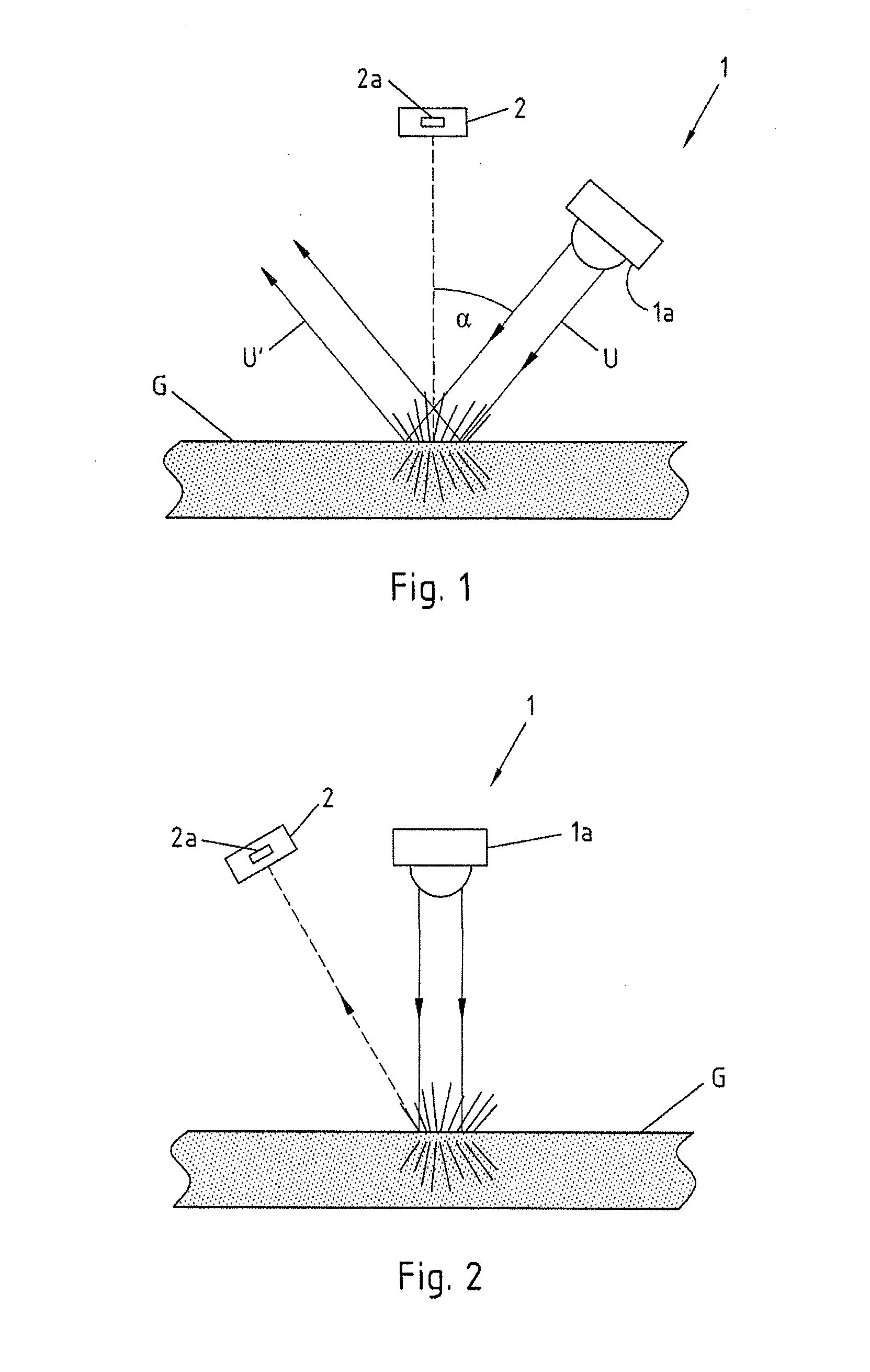
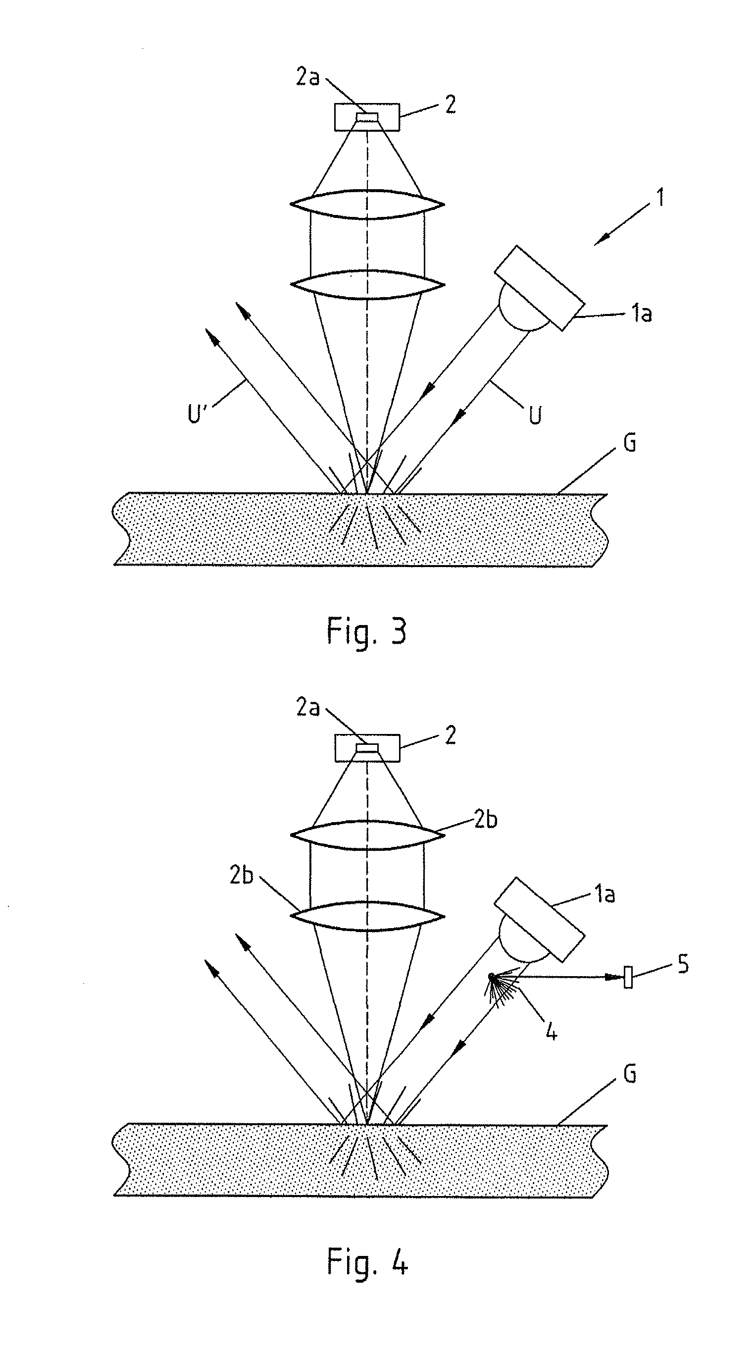
[0046]FIG. 1 shows an apparatus for determining the element occupancy on a surface by means of fluorescence. In particular, this comprises an apparatus for determining the tin contamination on a surface G of a glass product, in the present case on a float glass pane. The apparatus comprises a beam source 1 for generating UV radiation which excites tin atoms on the glass surface G to fluorescence. According to the invention, the beam source 1 comprises a light-emitting diode 1a (LED) emitting UV radiation U as a beam-producing element. This preferably comprises a diode which emits in the UV C range, preferably at about 280 nm in order to maximize the quantum yield in the tin fluorescence.

[0047]The apparatus further comprises a detector unit 2 for detecting the fluorescence radiation F emitted isotropically by the tin atoms present on the glass surface G. The detector unit 2 for its part comprises a detector element, in the present case a photodiode 2a, in which the incident beam powe...


PUM


Abstract

An apparatus for determining element occupancy on a surface includes a UV beam source comprising at least one UV light-emitting diode whose UV radiation excites the element to fluorescence and a detector unit for the detection of fluorescence radiation. The apparatus, in accordance with the invention, is characterized in that beam guidance is configured by alignment of the UV beam source and the detector unit relative to the surface and / or by using a wavelength-selective beam splitter in the beam path in such a manner that the UV radiation back-reflected from the surface is kept away from the detector unit.

Description

CROSS-REFERENCE TO RELATED APPLICATIONS[0001]This application is a National Phase Application of International Application No. PCT / EP2009 / 056926, filed on Jun. 5, 2009, which claims the benefit of and priority to German patent application no. DE 20 2008 007 542.4, filed on Jun. 5, 2008 and European patent application no. EP 08 104 278.0, filed on Jun. 5, 2008. The disclosures of the above applications are incorporated herein by reference in their entirety.FIELD OF THE INVENTION[0002]The invention relates to an apparatus for determining the element occupancy on a surface, in particular for determining the tin contamination on float glass, comprising a UV beam source comprising at least one UV light-emitting diode whose UV radiation excites the element to fluorescence, and comprising a detector unit (2) for detecting the fluorescence radiation.BACKGROUND[0003]In modern glass manufacture, plate glass which is used, for example, as window glass but also as a primary product for mirror a...

Claims


Application Information

Patent Timeline
IPC IPC(8): G01N21/64G01N21/958
CPCG01N21/645G01N21/896G01N2201/0625G01N2201/0624G01N21/94
Inventor OSTENDARP, HEINRICHPIONTEK, SIEGFRIED
Owner BOHLE
Why Eureka
Try Eureka