
Micromechanical system for detecting an acceleration

a micromechanical and acceleration technology, applied in the direction of speed/acceleration/shock measurement, measurement devices, instruments, etc., can solve problems such as mass structur

Active Publication Date: 2011-03-10
ROBERT BOSCH GMBH
View PDF11 Cites 30 Cited by
  • Summary
  • Abstract
  • Description
  • Claims
  • Application Information

AI Technical Summary

Benefits of technology

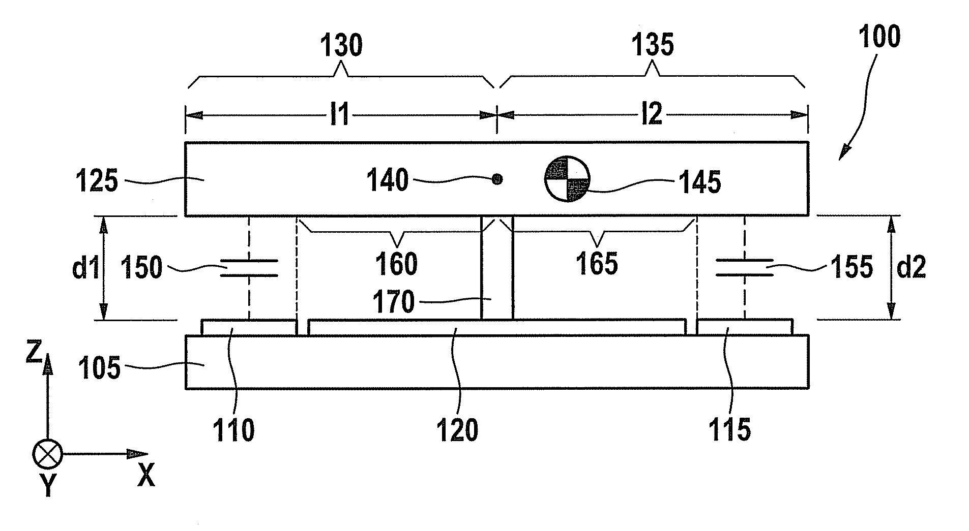
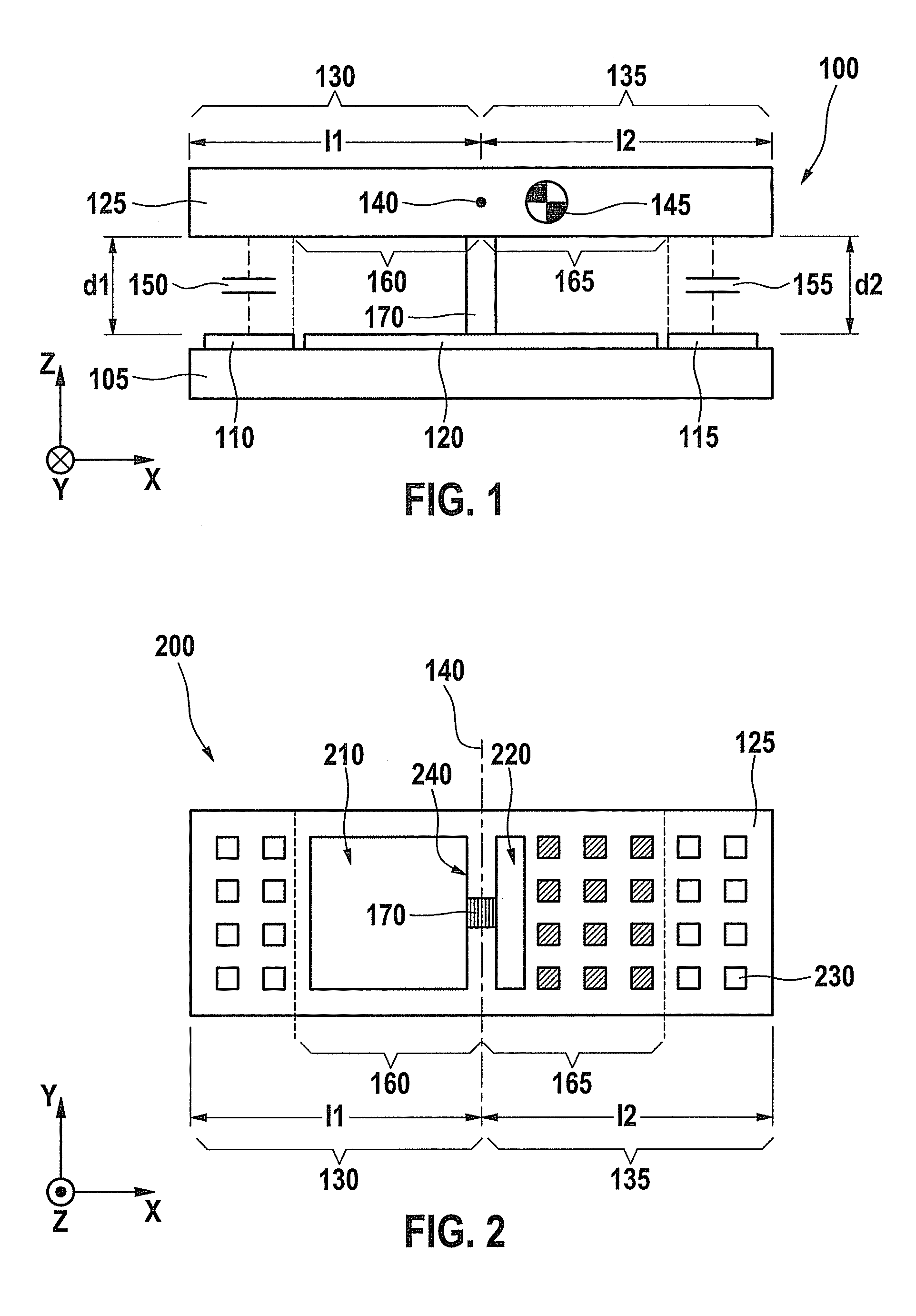
[0006]The present invention provides a micromechanical system having a rocker-like mass structure for detecting an acceleration in such a way that capacitors used to determine a deflection of the rocker-like mass structure are provided on the ends of the lever arms of the mass structure and sections of both lever arms have varying masses between the capacitors and the axis of rotation. In this manner, both lever arms may be of equal length, so that a clipping acceleration in both directions has an equal value and offset errors that occur in conventional micromechanical systems due to an asymmetrical design of the mass element are reduced.
[0007]Compared to a conventional micromechanical rocker structure, the capacitors for detecting an acceleration a are at a greater distance from the axis of rotation. As a result, the maximum possible change in the spacing of the electrodes of the capacitors and accordingly the relative capacitance change ΔC / C of each capacitor until clipping occurs is greater than in a conventional rocker structure. In designing the micromechanical system for identical sensitivity ΔC / CA, the clipping acceleration is therefore advantageously increased, typically by a factor of 2.
[0009]In an area between the substrate and the mass structure, an additional electrode may be provided on the substrate for shielding a structure lying under it from electrostatic influences due to the mass structure. To this end, the additional electrode may have the electrical potential of the mass structure. Nonetheless, parasitic surface charges on the additional electrode or the mass structure may be trapped, resulting in the action of electrostatic attraction forces between the additional electrode and the mass structure which may cause the mass structure to tilt, causing an offset error. By placing the additional electrode in the area of the axis of rotation instead of on the outer end of a lever arm, the tilting of the mass structure caused by such forces is reduced by a factor of 2.

Problems solved by technology

Nonetheless, parasitic surface charges on the additional electrode or the mass structure may be trapped, resulting in the action of electrostatic attraction forces between the additional electrode and the mass structure which may cause the mass structure to tilt, causing an offset error.

Method used


Image

  • Micromechanical system for detecting an acceleration
  • Micromechanical system for detecting an acceleration
  • Micromechanical system for detecting an acceleration

Examples


Embodiment Construction

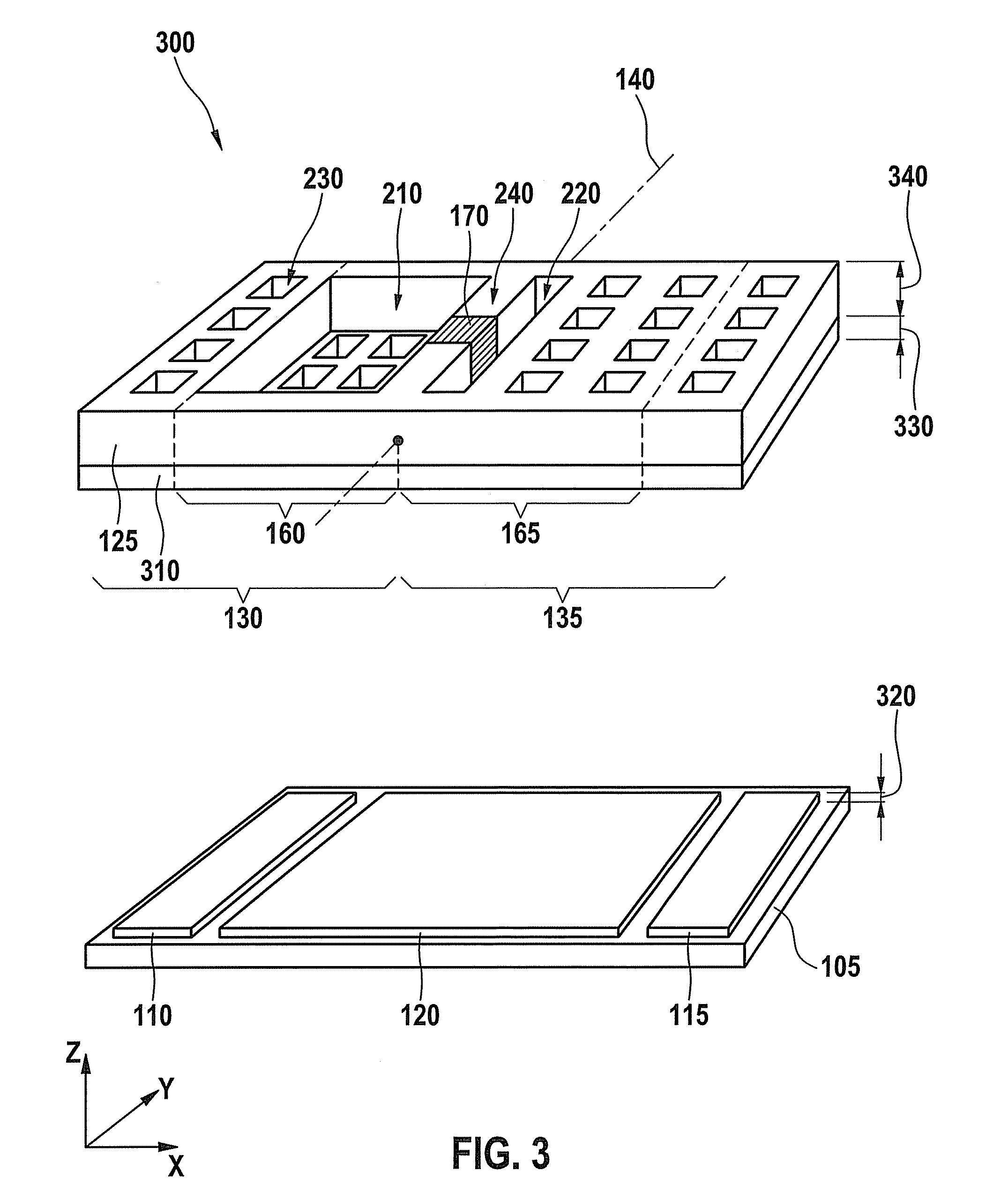
[0015]FIG. 1 shows a micromechanical system 100 in the form of an acceleration sensor for detecting an acceleration. A coordinate system specifies x, y and z directions. A first electrode 110, a second electrode 115 and a third electrode 120 are situated adjacent to one another on a substrate 105. A mass structure 125, which is oriented parallel to the surface of substrate 105 in an undeflected state, includes a first lever arm 130 and a second lever arm 135. Mass structure 125 is situated tiltably about an axis of rotation 140 in relation to substrate 105, so that first electrode 110 is located under an end section of first lever arm 130, second electrode 115 is located under an end section of second lever arm 135 and third electrode 120 is located in the area of a fastening structure 170 between first electrode 110 and second electrode 115. A torsion spring (not shown) acts counter to a tilting of mass structure 125 to substrate 105.

[0016]A center of gravity 145 of mass structure ...


PUM


Abstract

A micromechanical system for detecting an acceleration includes a substrate, a rocker-like mass structure having a first lever arm and a diametrically opposed second lever arm, the lever arms being situated tiltably at a distance to the substrate and about an axis of rotation to the substrate, and first and second electrodes being provided on the substrate. Each electrode is diametrically opposed to a lever arm and each lever arm includes a section extending from the axis of rotation which is located between the electrodes above an intermediate space. The two sections have different masses.

Description

BACKGROUND INFORMATION[0001]Acceleration sensors can be structured as micromechanical systems. Such sensors are used, for example, in motor vehicles where passenger protection devices (airbag, belt tightener, etc.) or driver assist systems (brake assist for stopping on a slope) evaluate an acceleration signal. One design of such micromechanical acceleration sensors determines an acceleration acting perpendicularly to a substrate with the aid of a rocker-like mass structure. The mass structure is situated tiltably in relation to the substrate about an axis of rotation running parallel to the substrate. A torsion spring holds the mass structure parallel to the substrate in its resting position. Two lever arms of the mass structure which are diametrically opposed with respect to the axis of rotation have varying lengths, so that a center of gravity of the mass structure is outside of the axis of rotation. If an acceleration acts on the rocker-like mass structure perpendicular to the su...

Claims


Application Information

Patent Timeline
IPC IPC(8): G01P15/125
CPCG01P15/125G01P2015/0831
Inventor CLASSEN, JOHANNES
Owner ROBERT BOSCH GMBH
Learn More