Double-resonance structure and method for investigating samples by DNP and/or ENDOR

a double resonance and endorse technology, applied in the field of double resonance structure for dnp experiments and/or endor experiments, can solve the problems of limited extent, high cost, limited sample volume that can be accommodated in the helix resonator, etc., to achieve high magnetic field strength, increase nmr sensitivity, and dissipate heat generated

Inactive Publication Date: 2011-03-03
JOHANN WOLFGANG GOETHE UNIV FRANKFURT AM MAIN
View PDF0 Cites 25 Cited by
  • Summary
  • Abstract
  • Description
  • Claims
  • Application Information

AI Technical Summary

Benefits of technology

[0016]The “strip resonator” may be formed by any strip conductor that is a suitable resonator for the HF field and at the same time can be used as part of the MW resonator. One example of such a strip resonator may be a “stripline resonator” or a “microstrip resonator”. By using such a strip resonator, HF fields for NMR transitions can be generated with sufficient strength. At the same time, the strip resonator forms a section of the MW resonator. The MW frequencies that are relevant here are so-called quasi-optical microwaves, and said section of the strip resonator may form a reflector for an MW resonator. At the MW frequencies that are relevant here, said section of the strip resonator or stripline resonator serves as a reflector of the MW resonator on which the microwaves are more or less optically reflected. This creates a more open structure in comparison with the helix resonator and this structure is advantageous with regard to the dissipation of heat, allowing the use of larger sample volume than is possible with the known helix resonator.
[0024]In an especially advantageous embodiment of the double-resonance structure, a place is provided for holding the sample, this location being connected to the strip resonator in a thermally conducting manner. For example, the place for holding the sample may be designed so that the sample held there is in direct contact with the strip resonator. Therefore, heat generated by absorption of microwaves in the sample can be dissipated efficiently by the strip resonator. This design is ideally suited for spectroscopic investigation of aqueous samples, which may be allowed to heat only slightly, in particular for investigation of biomolecules in aqueous solution.

Problems solved by technology

However, the sensitivity of NMR spectrometers reaches its limits in many applications, for example, in investigation of large biomolecules in vitro and in vivo.
The lack of sensitivity can be improved to a certain extent by applying a stronger external magnetic field, but this is possible only to a limited extent and at a very high cost.
However, the dimensions of the helix resonator correlate with the wavelength, and if the wavelength of the microwaves drops below a millimeter in strong magnetic fields according to the EPR conditions, the small size of the helix resonator limits the sample volume that can be accommodated in the helix resonator.
In the case of liquid samples, in particular aqueous samples, there is also the problem in using the known helix resonator that far less than its entire volume can be used for accommodating the sample volume because the sample would heat up too much from the application of microwaves.
The relatively strong losses, also known as “insertion losses”, result in the fact that, on the one hand, the MW field in the sample is considerably weaker than the field outside of the sample, and on the other hand, the sample is heated strongly.
For example, if biomolecules in aqueous solutions are to be investigated, high heating of the sample is out of the question because the biomolecules might be destroyed by heating.
If the MW power is reduced to prevent excessive heating of the sample, this leads to a weakening of the DNP and thus in turn to a negative effect on the NMR sensitivity.
This structure is suitable for ENDOR spectroscopy but not for DNP applications because the HF coil leads to a disturbance in the distribution of the electrical MW field over the sample volume, which leads to disadvantageous heating of the sample.

Method used


Image

  • Double-resonance structure and method for investigating samples by DNP and/or ENDOR
  • Double-resonance structure and method for investigating samples by DNP and/or ENDOR
  • Double-resonance structure and method for investigating samples by DNP and/or ENDOR

Examples


Embodiment Construction

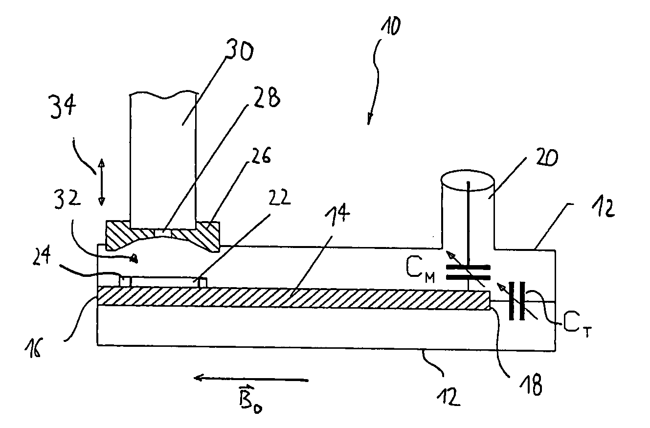
[0014]This object is achieved by a double-resonance structure according to Claim 1 and a method according to Claim 24. The method according to Claim 24 as such is known from the state of the art, but is characterized by the use of the inventive double-resonance structure. Advantageous further embodiments are defined in the dependent claims.

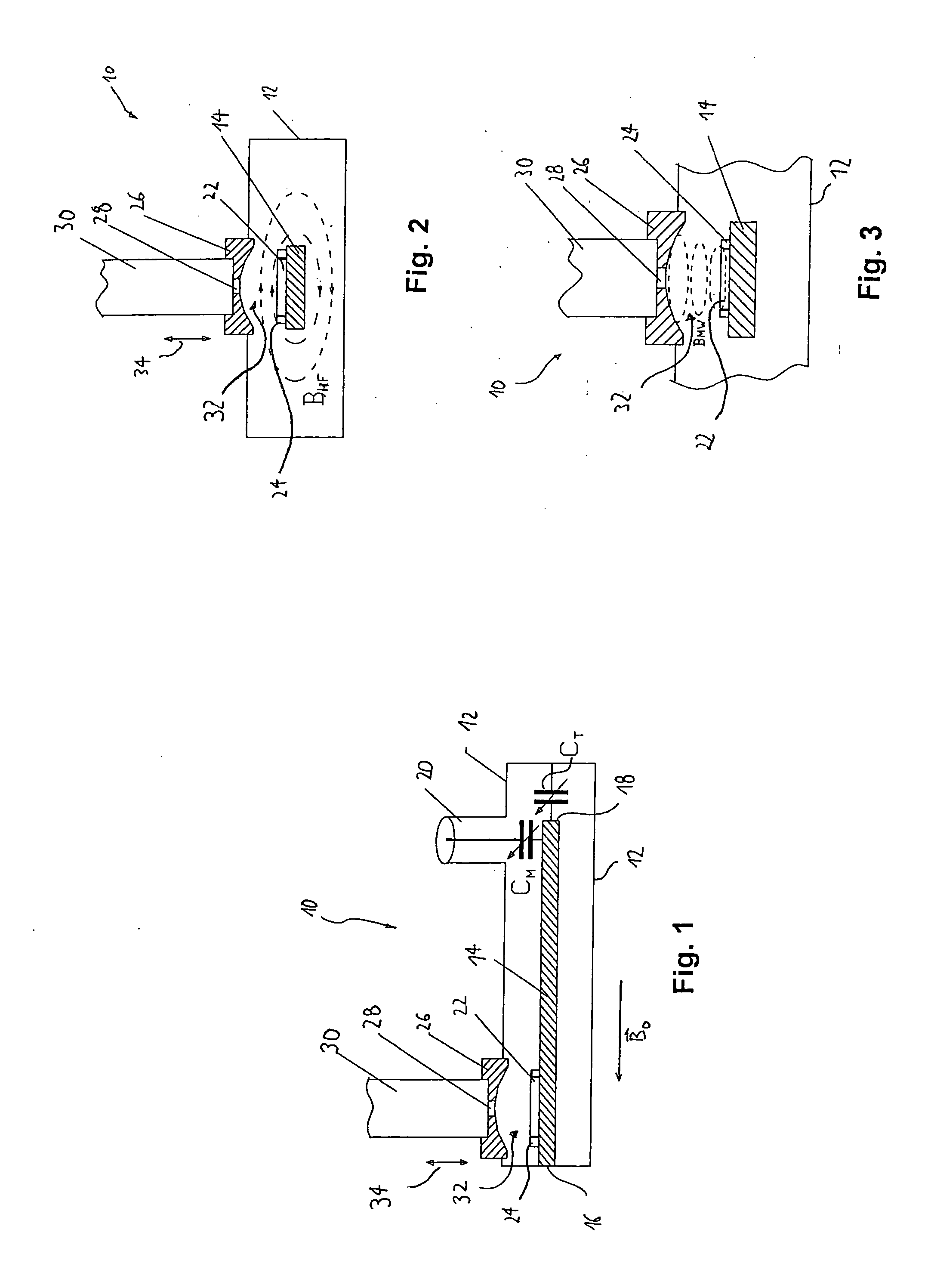
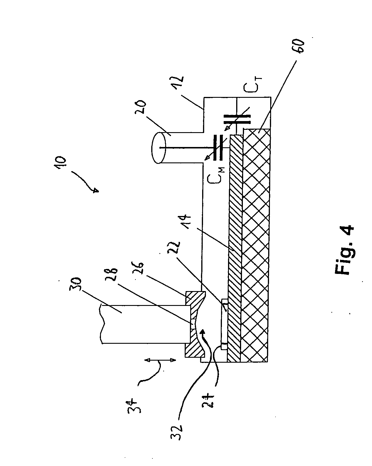
[0015]The double-resonance structure according to the present invention differs from that known from the state of the art in that the HF resonator is formed by a strip resonator, where a section of the strip resonator at the same time forms a part of the MW resonator.

[0016]The “strip resonator” may be formed by any strip conductor that is a suitable resonator for the HF field and at the same time can be used as part of the MW resonator. One example of such a strip resonator may be a “stripline resonator” or a “microstrip resonator”. By using such a strip resonator, HF fields for NMR transitions can be generated with sufficient strength. At the sam...


PUM


Abstract

A double-resonance structure for DNP-NMR experiments and / or ENDOR experiments and methods using such a double-resonance structure. The double-resonance structure comprises a microwave resonator for generating electromagnetic fields suitable for EPR and an HF resonator for generating electromagnetic fields suitable for NMR. The HF resonator is formed by a strip resonator, a section of the strip resonator at the same time forming a portion of the microwave resonator.

Description

[0001]The present application is a US National Phase application based on PCT / EP2009 / 002488, and, like the latter application, claims priority from German application Serial No. 10 2008 017 135.2, filed Apr. 3, 2008, which is incorporated herein by reference.BACKGROUND OF THE INVENTION[0002]The present invention relates to a double-resonance structure for DNP experiments and / or ENDOR experiments according to the preamble of claim 1. Furthermore, it relates to a method for investigating samples by DNP and / or ENDOR according to the preamble of claim 19.[0003]Nuclear magnetic resonance spectroscopy (NMR spectroscopy) is one of the most important spectrographic methods for elucidating the structure and dynamics of molecules, in particular in organic chemistry and biochemistry. However, the sensitivity of NMR spectrometers reaches its limits in many applications, for example, in investigation of large biomolecules in vitro and in vivo. The lack of sensitivity can be improved to a certain...

Claims


Application Information

Patent Timeline
IPC IPC(8): G01R33/34
CPCG01N24/12G01R33/282G01R33/62G01R33/4808G01R33/345
Inventor PRISNER, THOMASDENYSENKOV, VASYL
Owner JOHANN WOLFGANG GOETHE UNIV FRANKFURT AM MAIN
Why Eureka
Try Eureka