
Piezoelectric vibrator, piezoelectric vibrator manufacturing method, oscillator, electronic device, radio-controlled timepiece

a manufacturing method and piezoelectric technology, applied in the field of piezoelectric vibrators, can solve the problems of difficult to make the frequency fall within the nominal frequency range by the fine tuning step, and the frequency of the piezoelectric vibrating reed is changed

Inactive Publication Date: 2011-03-03
SII CRYSTAL TECH
View PDF3 Cites 9 Cited by
  • Summary
  • Abstract
  • Description
  • Claims
  • Application Information

AI Technical Summary

Benefits of technology

[0013]The present invention has been made in view of the foregoing, and an object of the present invention is to provide a piezoelectric vibrator and a manufacturing method thereof which is capable of achieving gettering in a state where the frequency change of the piezoelectric vibrating reed is suppressed.

Problems solved by technology

However, the piezoelectric vibrator of the related art has still the following problems.
When the constituent materials of the gettering material are deposited onto the piezoelectric vibrating reed, there is a problem in that the frequency of the piezoelectric vibrating reed is changed.
Moreover, when the frequency of the piezoelectric vibrating reed is changed before and after the gettering step, the frequency having fallen near the nominal frequency during the rough tuning step is changed before the fine tuning step, it may be difficult to make the frequency fall within the range of the nominal frequency by the fine tuning step.

Method used


Image

  • Piezoelectric vibrator, piezoelectric vibrator manufacturing method, oscillator, electronic device, radio-controlled timepiece
  • Piezoelectric vibrator, piezoelectric vibrator manufacturing method, oscillator, electronic device, radio-controlled timepiece
  • Piezoelectric vibrator, piezoelectric vibrator manufacturing method, oscillator, electronic device, radio-controlled timepiece

Examples


first embodiment

[0057]Hereinafter, a piezoelectric vibrator according to a first embodiment of the present invention will be described with reference to the drawings.

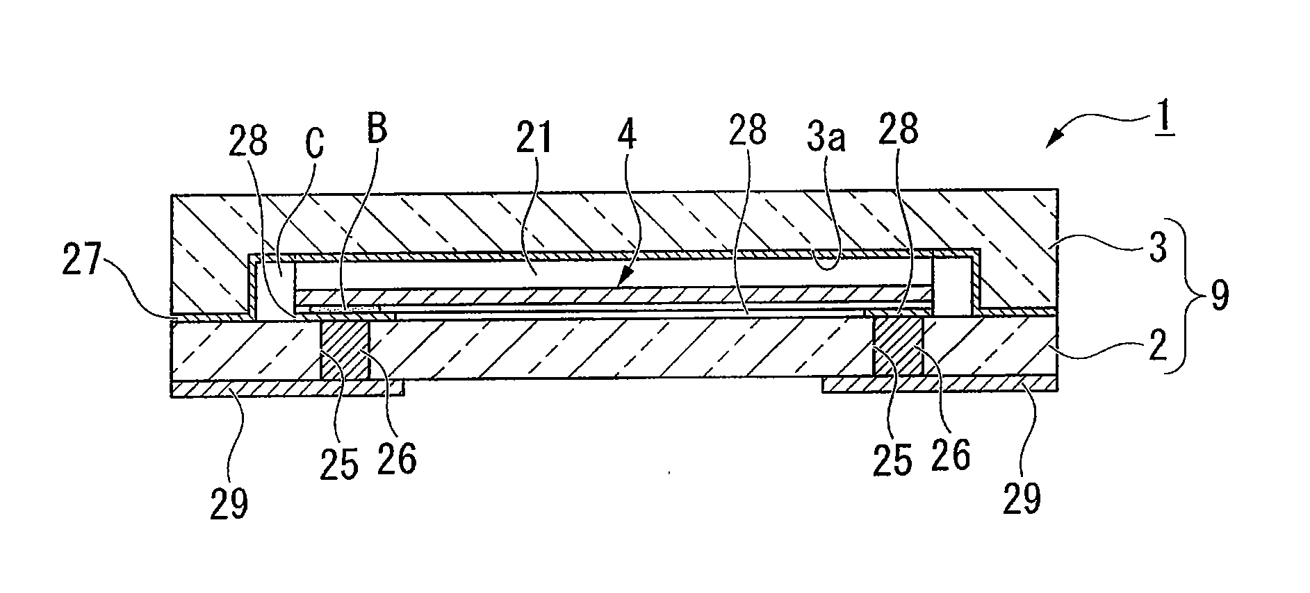
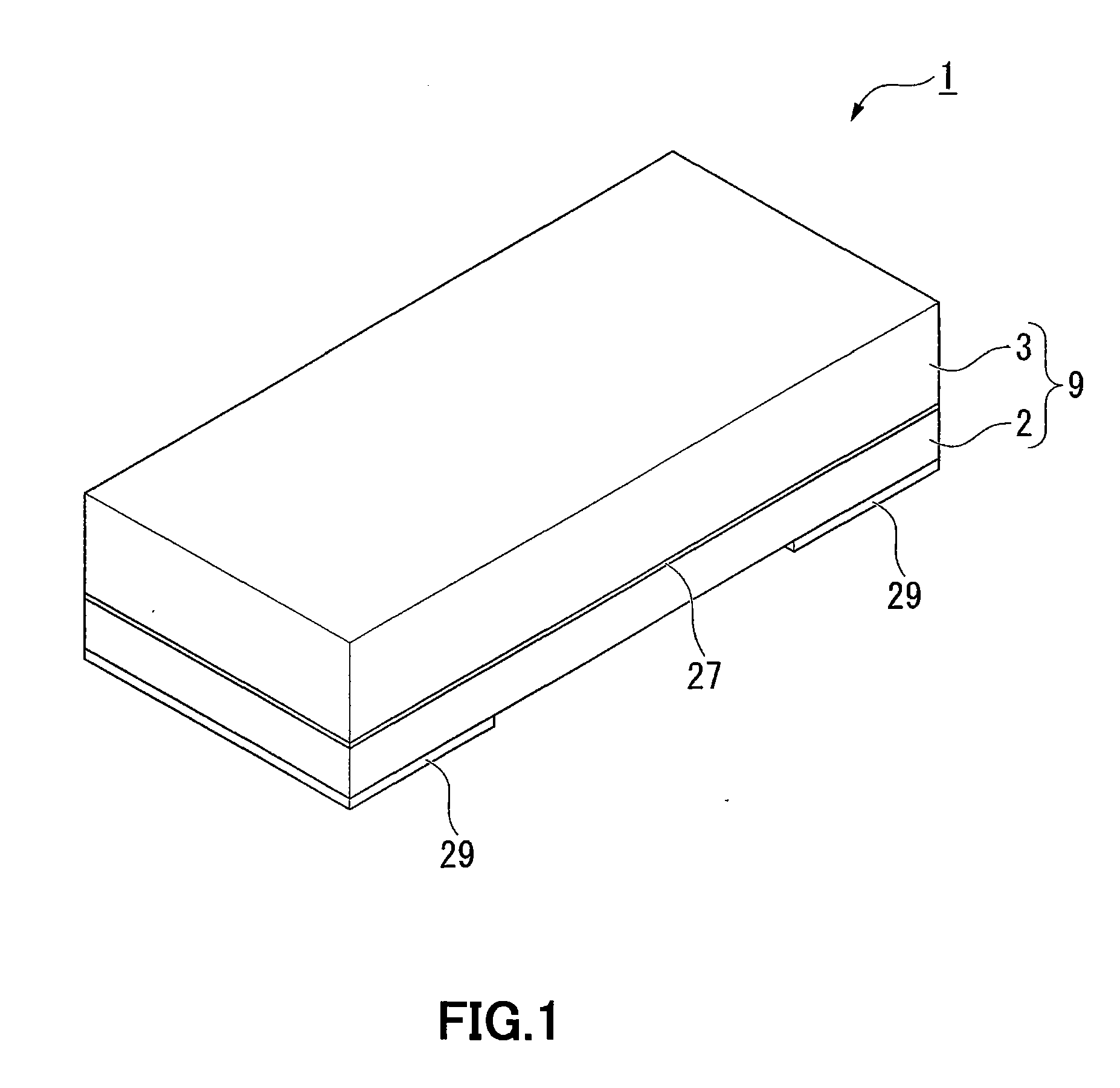
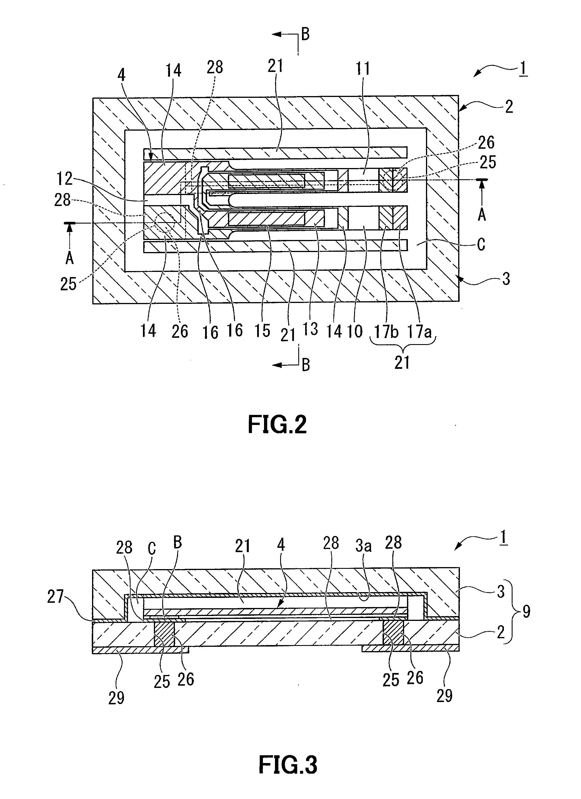
[0058]As shown in FIGS. 1 to 5, a piezoelectric vibrator 1 according to the present embodiment is a SMD-type piezoelectric vibrator including: a package 9 having a base board 2 and a lid board 3 which are bonded in a superimposed state and a cavity C formed between the two boards 2 and 3; and a piezoelectric vibrating reed 4 which is accommodated in the cavity C.

[0059]In FIG. 5, for better understanding of the drawings, illustrations of excitation electrodes 13, extraction electrodes 16, mount electrodes 14, and weight metal film 17 are omitted.

Piezoelectric Vibrating Reed

[0060]As shown in FIGS. 6 to 8, the piezoelectric vibrating reed 4 is a tuning-fork type vibrating reed which is made of a piezoelectric material such as quartz crystal, lithium tantalate, or lithium niobate and is configured to vibrate when a predetermined voltage is...

second embodiment

[0113]Next, a piezoelectric vibrator according to a second embodiment of the present invention will be described with reference to FIGS. 11 to 13. In the second embodiment, the same constituent elements as those in the first embodiment will be denoted by the same reference numerals, and description thereof will be omitted and only the points of difference will be described.

[0114]As shown in FIGS. 11 and 12, in a piezoelectric vibrator 70 of the present embodiment, instead of the metal film 27, a bonding film 71 made of a non-metallic material (for example, silicon) is formed on the entire inner surface of the lid board 3. The bonding film 71 is anodically bonded to the base board 2 at portions formed on the contacting surface of the lid board 3 and portions formed on the end surfaces of the shielding walls 21.

[0115]Moreover, as shown in FIG. 11, gettering materials 72 are formed in the cavity C. The gettering materials 72 are provided on both outer sides in the array direction of th...


PUM

PropertyMeasurementUnit
voltageaaaaaaaaaa
resonance frequenciesaaaaaaaaaa

Abstract

Providing a piezoelectric vibrator and a manufacturing method thereof which is capable of achieving gettering in a state where the frequency change of the piezoelectric vibrating reed is suppressed. Providing a piezoelectric vibrator 1 including: a package 9 having a base board 2 and a lid board 3 which are bonded in a superimposed state and a cavity C formed between both boards 2, 3; and a piezoelectric vibrating reed 4 and a gettering material 27 which are accommodated in the same cavity C, wherein a shielding wall 21 is provided in the cavity C so as to shield the piezoelectric vibrating reed 4 from the gettering material 27, and the shielding wall 21 is connected to both the base board 2 and the lid board 3.

Description

[0001]This application claims priority under 35 U.S.C. §119 to Japanese Patent Application No. 2009-194475 filed on Aug. 25, 2009, the entire content of which is hereby incorporated by referenceBACKGROUND OF THE INVENTION[0002]1. Field of the Invention[0003]The present invention relates to a piezoelectric vibrator, a manufacturing method of the piezoelectric vibrator, and an oscillator, an electronic device, and a radio-controlled timepiece.[0004]2. Description of the Related Art[0005]Recently, a piezoelectric vibrator using a piezoelectric vibrating reed made of a piezoelectric material such as quartz has been used in cellular phones and portable information terminals as the time source, the timing source of a control signal, a reference signal source, and the like. As the piezoelectric vibrating reed, for example, a tuning-fork type piezoelectric vibrating reed having a pair of vibrating arms is used.[0006]As the piezoelectric vibrator of this type, an SMD (Surface Mount Device)-t...

Claims


Application Information

Patent Timeline
Patent Type & Authority Applications(United States)
IPC IPC(8): H01L41/053H01L41/22H01L23/02H01L23/26H03B5/32H03H3/02H03H9/02
CPCY10T29/42G04R20/10
Inventor ONITSUKA, OSAMUSUGAMA, KAZUYOSHI
Owner SII CRYSTAL TECH
Learn More