
Microgrid frequency control method and system

A technology of frequency control and micro-grid, applied in the direction of single-network parallel feeding arrangement, reducing/preventing power oscillation, etc., can solve problems affecting stable operation of the system, unstable system frequency, and low effectiveness

Active Publication Date: 2018-11-09
ELECTRIC POWER RES INST OF GUANGDONG POWER GRID
View PDF4 Cites 0 Cited by
  • Summary
  • Abstract
  • Description
  • Claims
  • Application Information

AI Technical Summary

Problems solved by technology

However, with the increase of the capacity of the inverter power supply, its low inertia will affect the stable operation of the system, especially in the island microgrid, where the distributed new energy and load fluctuations are more obvious, the low inertia will cause the system frequency to fluctuate. Stablize
[0004] For this reason, many scholars have proposed control methods of virtual synchronous generators, but these methods have certain defects in the selection of models and the performance of secondary frequency modulation, which makes the effectiveness of control low.

Method used


Image

  • Microgrid frequency control method and system
  • Microgrid frequency control method and system
  • Microgrid frequency control method and system

Examples


Embodiment Construction

[0026] In order to make the object, technical solution and advantages of the present invention clearer, the present invention will be further described in detail below in conjunction with the accompanying drawings and embodiments. It should be understood that the specific embodiments described here are only used to explain the present invention, and do not limit the protection scope of the present invention.

[0027] In the following description, the embodiments of the microgrid frequency control method of the present invention will be described first, and then the embodiments of the microgrid frequency control system of the present invention will be described.

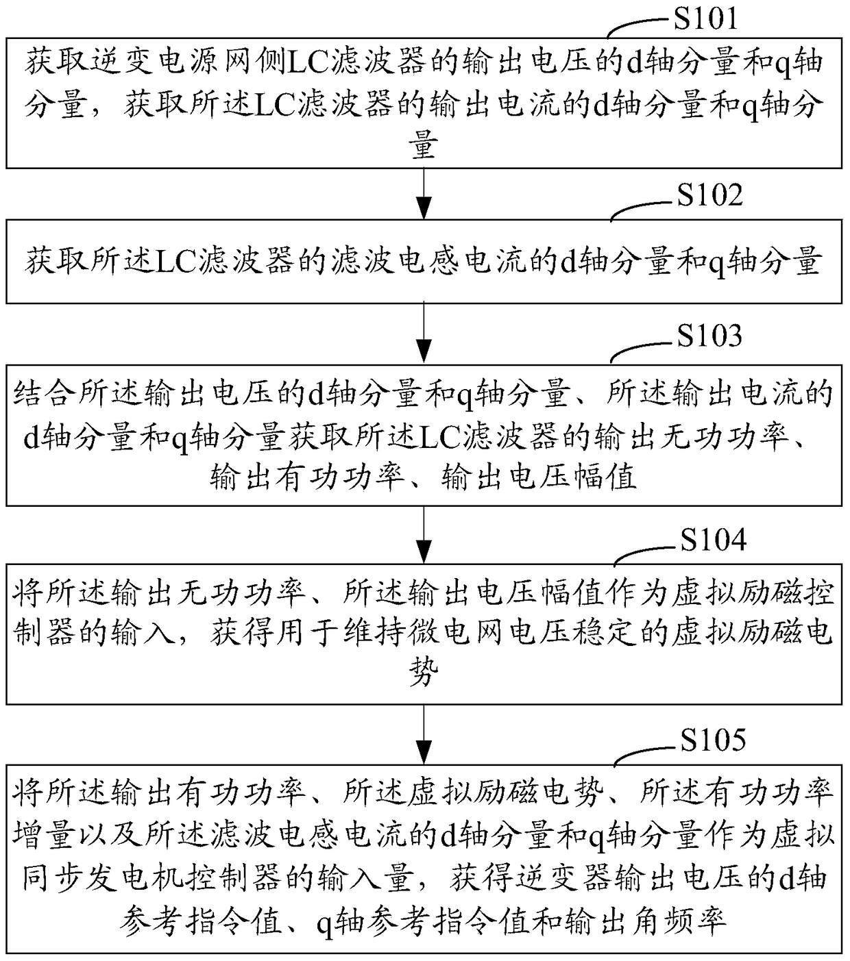
[0028] see figure 1 Shown is a schematic flow chart of an embodiment of the microgrid frequency control method of the present invention. Such as figure 1 As shown, the microgrid frequency control method of this embodiment includes:

[0029] Step S101: Obtain the d-axis component and q-axis component of the output v...


PUM


Abstract

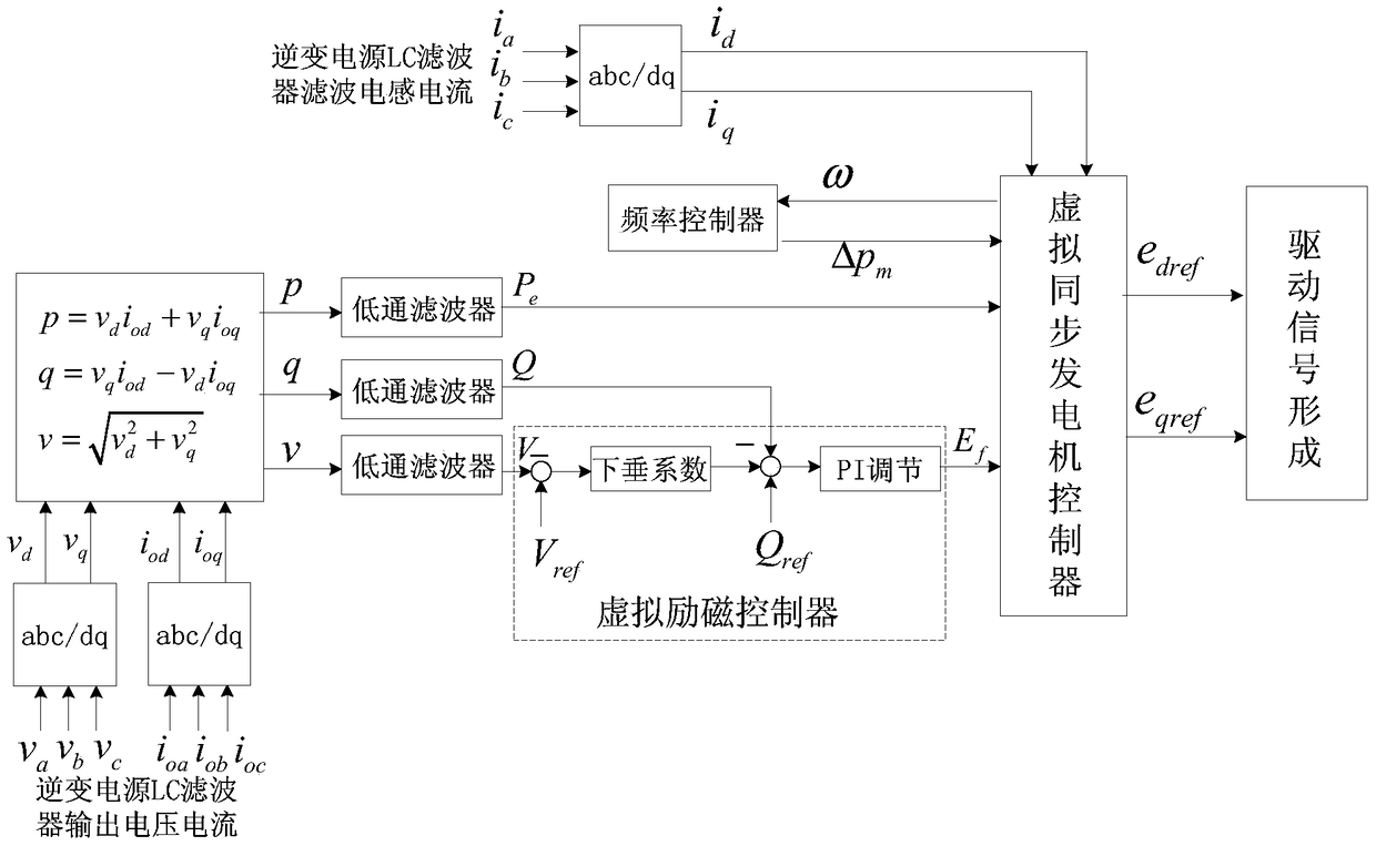
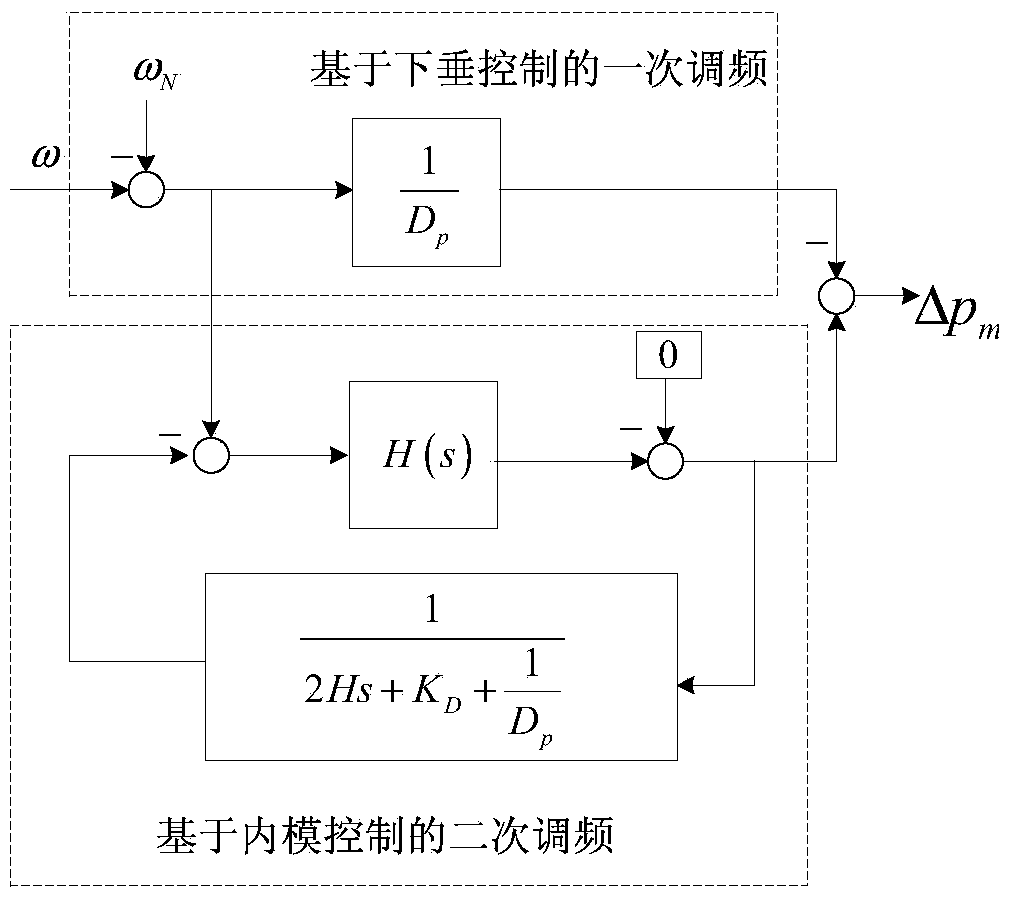
A micro power grid frequency control method and a system are provided, wherein the method comprises the steps of obtaining d-axis and q-axis components of an output voltage, an output current and a filtering inductance current of an LC filter at the grid side of an inversion power supply; obtaining the output reactive power, the output active power and an output voltage amplitude of the LC filter in combination with the d-axis and the q-axis components of the output voltage and the output current; obtaining a virtual excitation electromotive force by taking the output reactive power and the output voltage amplitude as the input of a virtual excitation controller; obtaining an active power increment by inputting an output angular frequency of a virtual synchronous generator controller into a frequency controller; and obtaining a d-axis and a q-axis reference instruction value and an output angular frequency of the inverter output voltage by taking the output active power, the virtual excitation electromotive force, the active power increment and the d-axis component and the q-axis component of the filtering inductance current as the input of the virtual synchronous generator controller. According to the invention, the micro power grid frequency change caused by load disturbance can be effectively inhibited; and the island micro power grid can be operated stably.

Description

technical field [0001] The invention relates to the field of new energy power conversion, in particular to a microgrid frequency control method and system. Background technique [0002] With the depletion of energy and the increasingly serious environmental pollution, distributed energy has developed rapidly, and the traditional centralized power system is facing a profound change to distributed power generation. Among them, microgrid is an effective way to realize intelligent management of distributed power. [0003] However, the microgrid lacks the voltage and frequency support of the main grid in the island operation mode, and needs to rely on the control of the inverter itself to achieve stable operation of the system. For this reason, scholars at home and abroad have successively proposed some control methods, such as V / F control, droop control, and anti-droop control. However, with the increase of the capacity of the inverter power supply, its low inertia will affect...

Claims


Application Information

Patent Timeline
Patent Type & Authority Patents(China)
IPC IPC(8): H02J3/24H02J3/46
Inventor 唐酿盛超翁洪杰陈萌肖湘宁陶顺袁敞孙闻陈锐张俊峰朱良合罗运松张毅超吴晓宇刘正富安然然赵艳军
Owner ELECTRIC POWER RES INST OF GUANGDONG POWER GRID
Learn More