
Optoelectronic device and process for making same

a technology of optoelectronic devices and process, applied in the direction of semiconductor devices, electrical devices, solid-state devices, etc., can solve the problem that the photo diode formed by silicon has low light absorption efficiency to invisible light, and achieve the effect of improving light absorption efficiency

Inactive Publication Date: 2011-03-03
PIXART IMAGING INC
View PDF7 Cites 0 Cited by
  • Summary
  • Abstract
  • Description
  • Claims
  • Application Information

AI Technical Summary

Benefits of technology

The present invention provides an optoelectronic device with enhanced light absorption efficiency for different wavelengths of light. This is achieved by making a substrate with a region made of a different material, such as silicon germanium or silicon carbide, and forming a photo diode in this region using ion implantation. The optoelectronic device can also include an electronic circuit coupled to the photo diode. The process for making the optoelectronic device involves etching a region in the substrate, filling it with the second material, and forming a photo diode. The technical effect of this invention is to improve the device's ability to absorb light and convert it into electrical signals.

Problems solved by technology

However, such photo diode formed by silicon has low light absorption efficiency to invisible light.

Method used


Image

  • Optoelectronic device and process for making same
  • Optoelectronic device and process for making same
  • Optoelectronic device and process for making same

Examples


Embodiment Construction

[0015]The drawings as referred to throughout the description of the present invention are for illustration only, to show the interrelationships between the process steps and between the layers, but not drawn according to actual scale.

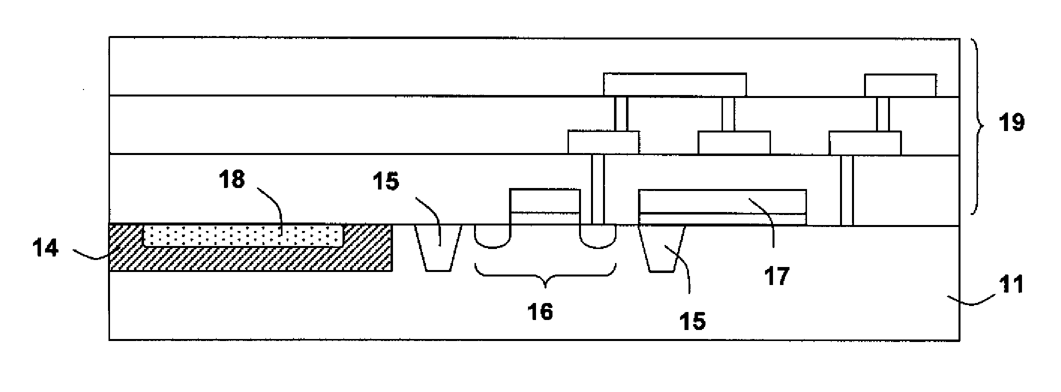
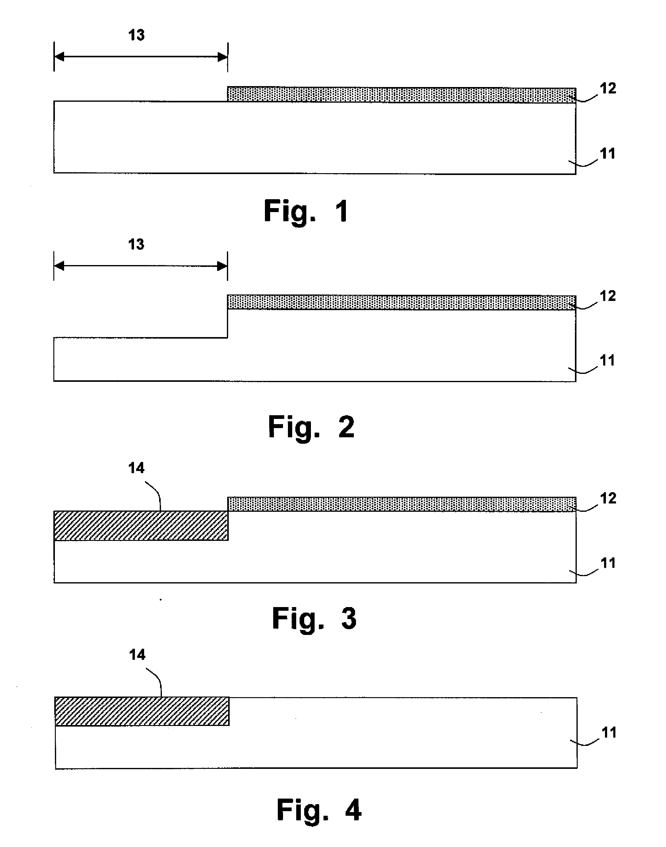
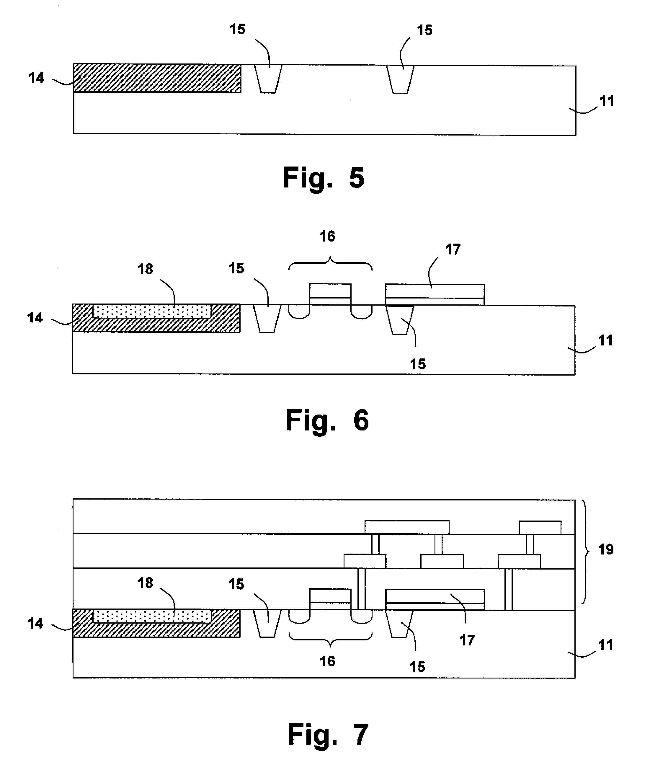
[0016]FIGS. 1-7 illustrate an embodiment of the present invention. Referring to FIG. 1, a substrate 11 made of a first material, such as silicon, is provided. A masking layer 12 is formed on the substrate 11 (e.g., by deposition); the masking layer 12 is made of a material such as oxide (e.g., silicon dioxide). The masking layer 12 has a pattern defined by photolithography and etch to expose a region 13. Next, as shown in FIG. 2, the substrate 11 is etched in accordance with the pattern of the masking layer 12. And next, referring to FIG. 3 and FIG. 4, a material layer 14 made of a second material different from the first material of the substrate 11, is formed in the etched region 13 of the substrate 11, and then the masking layer 12 is removed. Accord...


PUM

PropertyMeasurementUnit
temperatureaaaaaaaaaa
energy gapaaaaaaaaaa

Abstract

The present invention discloses an optoelectronic device, comprising: a substrate made of a first material; a region in the substrate, the region being made of a second material different from the first material; and a photo diode formed in the region by ion implantation. The second material for example is silicon germanium (Si1-xGex) or silicon carbide (Si1-yCy), wherein 0<x,y<1.

Description

BACKGROUND OF THE INVENTION[0001]1. Field of Invention[0002]The present invention relates to an optoelectronic device and a process for making same; particularly, it relates to an integrated device of an electronic circuit and a photo diode having enhanced light absorption efficiency to light of different wavelengths, and a process for making same.[0003]2. Description of Related Art[0004]An optoelectronic device, such as a sensor, is often required in digital image processing. The sensor generally includes a photo diode and an electronic circuit, and an image received is converted to an electronic signal output.[0005]Conventionally, a photo diode is constituted by a PN junction formed in a silicon substrate. However, such photo diode formed by silicon has low light absorption efficiency to invisible light. Accordingly, it is desired to provide a device having better light absorption efficiency for invisible light applications, such as infrared sensor.SUMMARY OF THE INVENTION[0006]An...

Claims


Application Information

Patent Timeline
Patent Type & Authority Applications(United States)
IPC IPC(8): H01L31/102H01L21/20
CPCH01L21/02381H01L21/02529H01L21/02532H01L21/0262Y02E10/50H01L27/14689H01L31/103H01L31/1812H01L21/02658
Inventor HSU, HSIN-HUICHIEN, HO-CHINGCHEN, CHING-WEIHUANG, SEN-HUANG
Owner PIXART IMAGING INC
Learn More