System and Method for Regulating Flow in Fluidic Devices

Active Publication Date: 2011-02-24
O I CORP
View PDF75 Cites 36 Cited by
  • Summary
  • Abstract
  • Description
  • Claims
  • Application Information

AI Technical Summary

Benefits of technology

[0009]Disclosed is a system and method of regulating the flow of a fluidic device. An exemplary fluidic device is an analytical detector, and the system and method described herein can be used to provide constant sample flow at a sample detector. The system uses one or more controllers to monitor and control the addition of transport medium, sample, and reagents to one or more analytical streams in order to maintain a constant flow of the analytical streams at one or more analytical detectors. Typically, the flow rate through the analytical stream is controlled by the controllers to properly sequence the addition of the sample and one or more reaction reagents and to permit one or more reaction processes prior to constant flow analysis by the detectors. Embodiments of the system and method provide a sample pipeline with high sample throughput independent of the complexity of the reaction, without the disadvantages of peristaltic pumps or excessively wasteful flow quantities of sample or reagent. Embodiments allow for the dynamic injection of samples and reagents into the sample pipeline on an analysis-by-analysis basis where sample and / or reagent volumes can be optimized for the specific measurement. The result embodies an automated device that, like a discrete batch analysis method, provides a high level of automation, minimizes sample volumes, reagent volumes, and waste generation, while maintaining the continuous flow sample pipeline and throughput capabilities of continuous flow analysis.
[0010]An exemplary implementation of the system comprises one or more analytical streams flowing through a pumping system and flow control module, a sample introduction module, a sample reaction module, and a sample detection module. An exemplary pumping system and flow control module comprise a pump, a back pressure regulator and one or more fluidic flow controllers. The pump draws transport medium from a reservoir and directs it to the one or more analytical streams. The back pressure regulator positioned downstream of the pump maintains a constant pressure of the transport medium to each of the analytical streams. The fluidic flow controller maintains a constant flow rate of transport medium in each of the analytical streams. In one implementation of the system, the sample introduction module comprises a syringe pump and an isolation loop. In an embodiment, the sample reaction module includes inlets for the introduction of reagents into the analytical streams and one or more reaction devices, some of which may be user-configurable. The pumping system and flow control module reduce the flow rate of transport medium to compensate for the introduction of sample and reagents into the analytical streams, thereby maintaining a constant flow at the sample detection module.
[0012]Also disclosed is an embodiment of a system for intermittent introduction of sample and reagent(s) into a continuously flowing carrier stream. The system includes a means to propel the carrier stream by a non-pulsatile mechanism, a sample injection valve to introduce the sample into the carrier stream and a means to introduce discrete aliquots of reagents into the continuously flowing stream at pre-programmed intervals. The non-pulsatile characteristic of the carrier stream pumping mechanism of the system allows the location of the sample within the carrier stream to be known at any time following sample introduction into the carrier stream. At least one reagent is added to the sample in the carrier stream when the sample carrier stream is disposed at a desired location in the sample and reagent addition system.

Problems solved by technology

The major drawbacks to continuous flow analysis include the lack of ability to program tests per sample and excessive reagent usage as they are pumped continuously during the analytical process.
Beyond the analytical difficulties with current methods, continuous flow instruments are negatively impacted by the use of peristaltic pumps to provide motive force for samples and reagents.
These pumps limit the performance of continuous flow systems through the peristaltic action that is an intrinsic characteristic of peristaltic pumps.
This action causes pulsations in the fluid path that may adversely affect the accurate quantification of analytes passing through the fluidic device to a sample detector.
Although they are relatively inexpensive, peristaltic pumps can be problematic for common applications involving sample measurements.
Furthermore, the tubing used in peristaltic pumps often fails due to collapse (i.e., loss of elasticity).
This tubing failure generates uneven, or non-reproducible flows, for the different channels of analyte and / or reagents being transported.
Other pumps are also not particularly suitable for a variety of reasons.
For example, replacing peristaltic pumps with syringe pumps is very expensive.
Moreover, other types of air displacement pumps are not suitable replacements for peristaltic pumps, because they have problems with gas solubility (e.g., air bubbles coming out of solution in the detector) and gas compressibility in the analyte transport process.
However, discrete batch analysis has major drawbacks that include (a) decreased sample throughput or number of tests per hour since each sample reaction sequence is treated discretely or independently thereby not enabling a pipeline to be established; and (b) the inability to perform in-line sample preparation.

Method used


Image

  • System and Method for Regulating Flow in Fluidic Devices
  • System and Method for Regulating Flow in Fluidic Devices
  • System and Method for Regulating Flow in Fluidic Devices

Examples


example

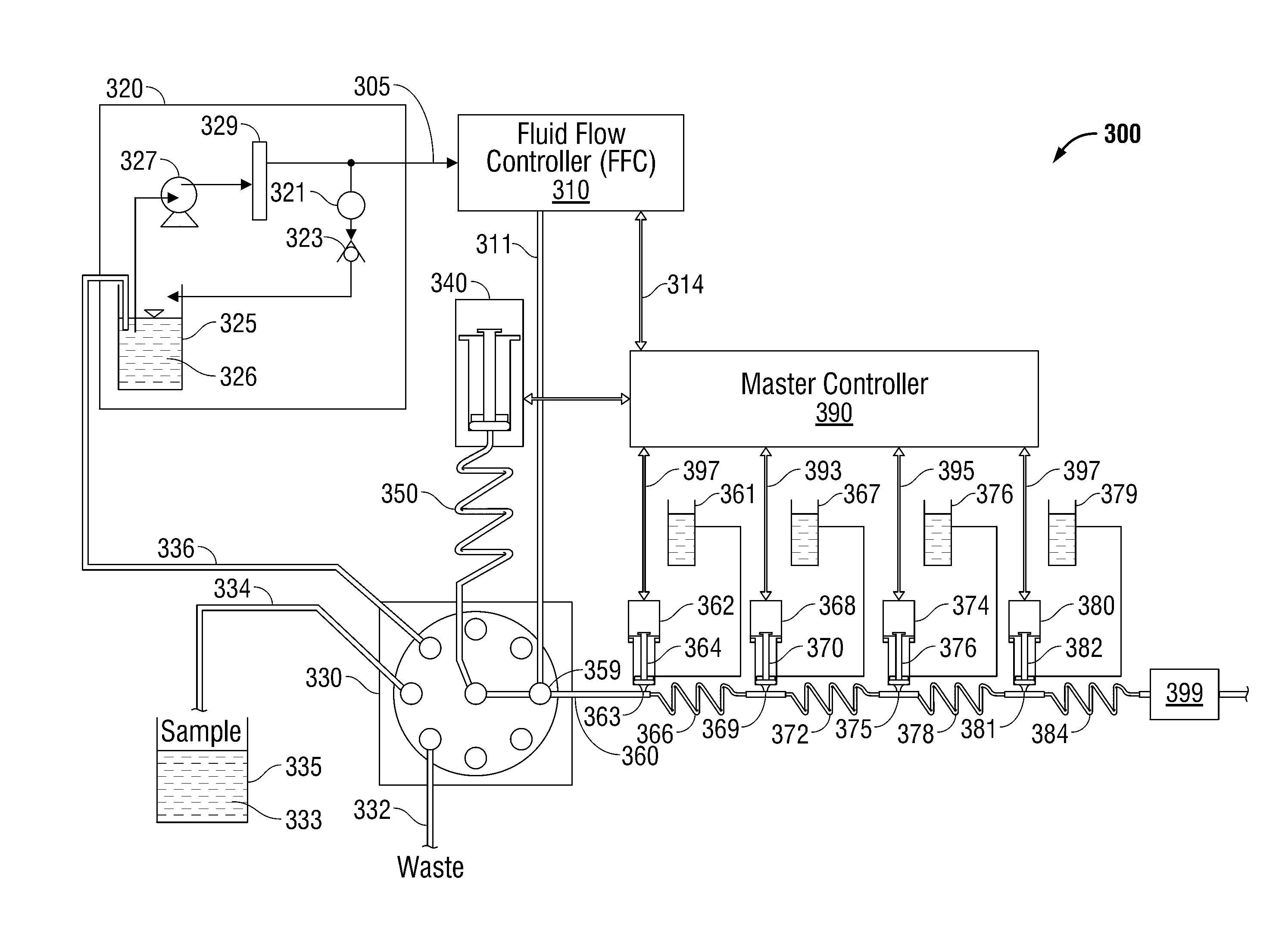
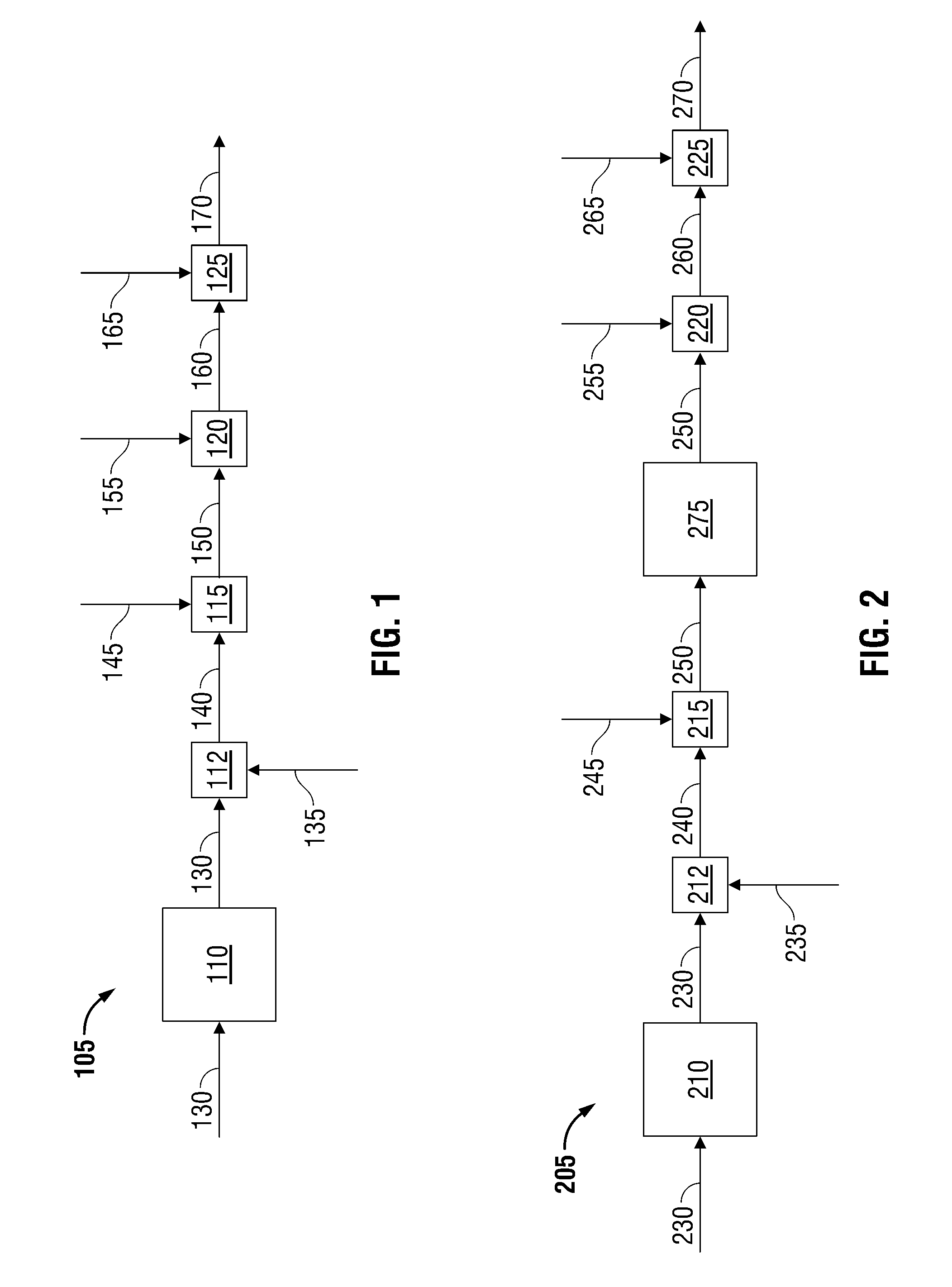
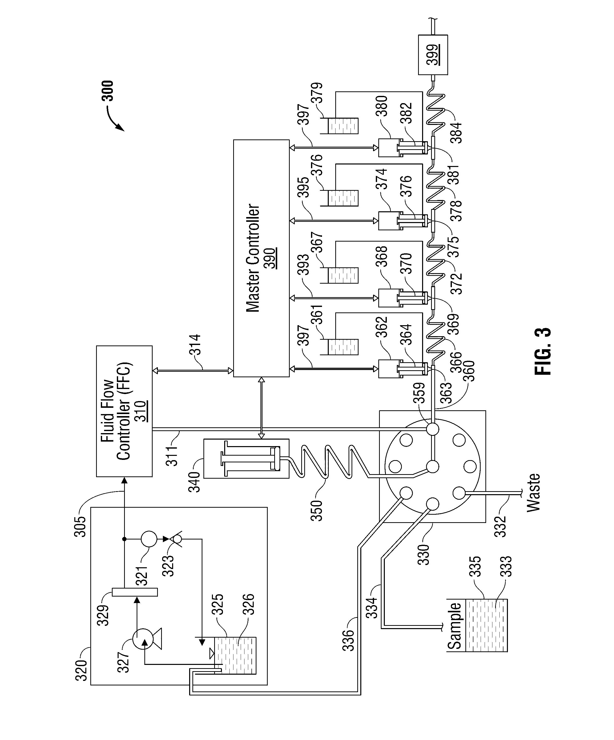
[0043]An example application of sample and reagent addition process 105 is in the determination of nitrate in water samples. In preparation for sample processing, a carrier stream was aspirated into a syringe through a valve aligned with a reservoir of deionized water. The valve was then switched to place the syringe in-line with the primary fluidic conduit, and the carrier was pumped downstream through the entire fluidic conduit and into a flow cell where a water baseline was established. This apparatus corresponded with pump 110 in FIG. 1.

[0044]Once the water baseline was established, the sample was injected into the carrier stream at sample addition point 112 in FIG. 1. Subsequently, a quantity, of ammonium chloride (R1) was pulsed into the carrier stream on top of the sample zone in the carrier as it passed reagent addition point 115 in FIG. 1 and pumped into a mixing device and a reaction device. The carrier / R1 combination was then pumped through a conduit coated with cadmium t...


PUM


Abstract

Disclosed are a system and method for regulating flow in an exemplary fluidic device comprising a fluidic stream carrying a transport medium, sample and one or more reagents for analysis and synthesis of reaction products. The flow rate of the fluidic stream is maintained constant by adjusting the flow rate of transport medium to compensate for the introduction of sample and reagents. An embodiment controls the flow rate of transport medium using a pump, a back pressure regulator, and a variable-sized orifice. Single and multiple channel embodiments are disclosed.

Description

CROSS-REFERENCE TO RELATED APPLICATIONS[0001]This application claims the benefit of U.S. Provisional Application No. 61 / 017,867 filed on 31 Dec. 2007, which is hereby incorporated by reference. This application further claims the benefit of U.S. Provisional Application No. 61 / 137,027 filed on 25 Jul. 2008, which is hereby incorporated by reference.BACKGROUND OF THE INVENTION[0002]1. Field of the Invention[0003]This invention relates to the field of flow regulation in fluidic devices. Specifically, this invention relates to the field of flow regulation in fluidic devices used in the field of chemical synthesis and analysis.[0004]2. Background of the Invention[0005]Many different methods have been developed for sample preparation, chemical synthesis and chemical analysis. Typical methods include continuous flow analysis and discrete batch analysis. Continuous flow analysis includes establishing a sample pipeline to enable high sample throughput independent of the complexity of the rea...

Claims


Application Information

Patent Timeline
IPC IPC(8): G01N33/18G01N33/00
CPCB01L3/502738Y10T436/173076B01L2200/0642B01L2200/10B01L2200/14B01L2200/16B01L2400/0478B01L2400/082F04B19/006Y10T436/11Y10T436/25Y10T436/118339Y10T436/2575Y10T436/117497B01L2200/0621F04B13/02F04B49/106
Inventor ERICKSON, GARY L.RANGER, CRAIG
Owner O I CORP
Why Eureka
Try Eureka