
Current-mode control switching regulator and operations control method thereof

a switching regulator and operation control technology, applied in the direction of dc-dc conversion, power conversion systems, instruments, etc., can solve the problems of subharmonic oscillation and go out of control, the phase compensation of an error amplification circuit which amplifies the voltage difference between the output voltage and the reference voltage becomes complicated, and the response speed to fluctuation in output voltage is slow. , to achieve the effect of suppressing fluctuation in frequency characteristics, preventing subharmonic oscillation, and wide variabl

Active Publication Date: 2011-02-24
NISSHINBO MICRO DEVICES INC
View PDF22 Cites 28 Cited by
  • Summary
  • Abstract
  • Description
  • Claims
  • Application Information

AI Technical Summary

Benefits of technology

[0016]The present invention has been made to solve the above problems and may provide a current-mode control switching regulator capable of preventing subharmonic oscillation in a wide input / output voltage range and a wide variable frequency range with a simple circuit and suppressing fluctuation in frequency characteristics. Specifically, a step-down switching regulator changes the inclination of a slope voltage in accordance with an input voltage and an oscillation frequency, while a step-up switching regulator changes the inclination of a slope voltage in accordance with an output voltage and an oscillation frequency. The present invention may also provide the operations control method of the current-mode control switching regulator.

Problems solved by technology

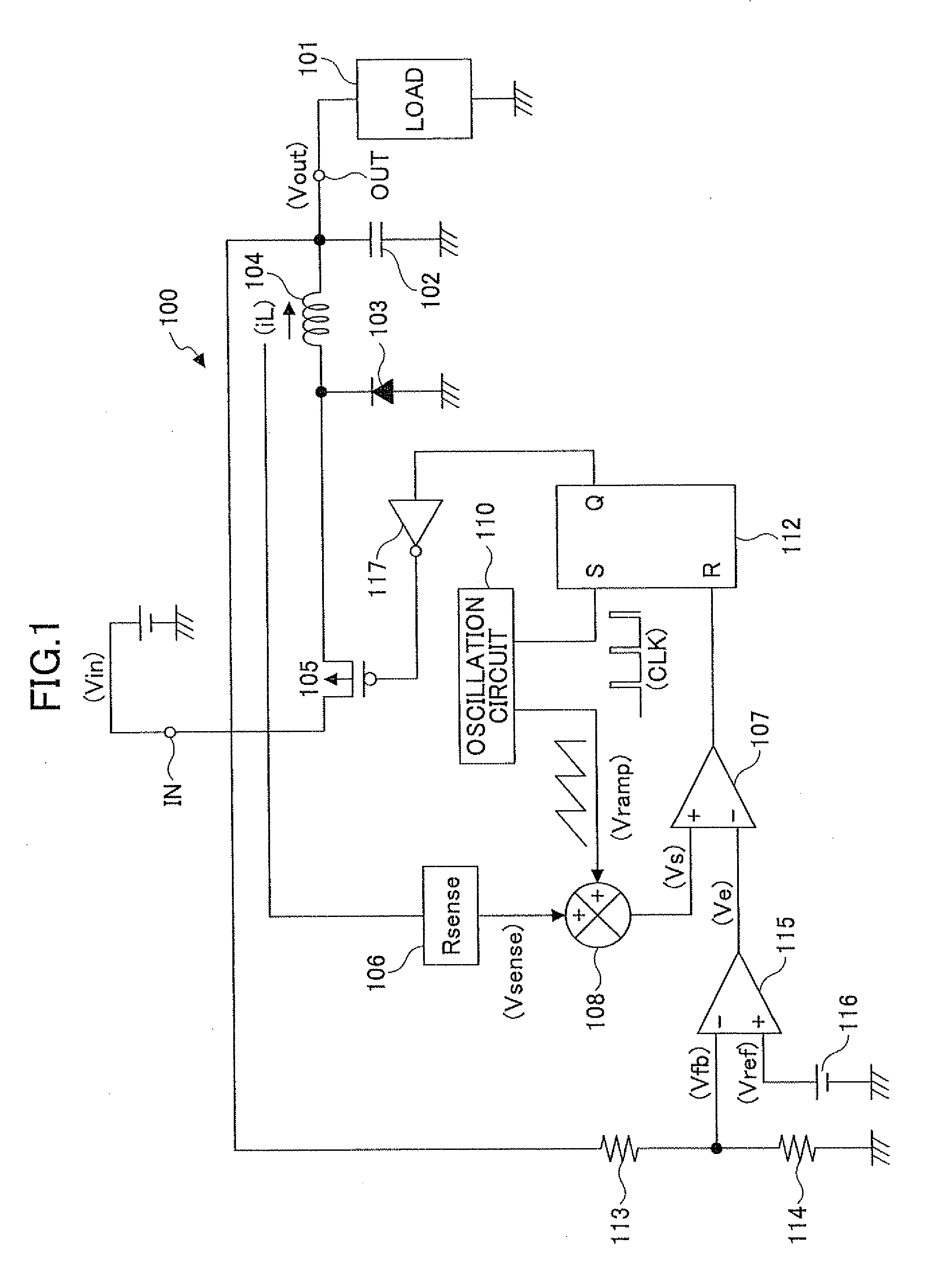
However, since the voltage-mode control switching regulators detect a returned signal from the output voltage, their response speed to fluctuation in the output voltage is slow and the phase compensation of an error amplification circuit which amplifies the voltage difference between the output voltage and the reference voltage becomes complicated.
However, it is known that, when the on-duty cycle of PWM control exceeds 50%, the current mode control switching regulators cause subharmonic oscillation and go out of control.
However, although subharmonic oscillation can be prevented when excessive slope compensation is performed, the advantages of current feedback are lost.
As a result, the current-mode control switching regulator operates like the voltage-mode switching regulator to degrade its controllability.
However, in this case, since the slope compensation amount is changed in accordance with an input voltage and an output voltage, the circuit becomes complicated.
Furthermore, since the general-purpose IC of the switching regulator generally has an external resistor for generating the divided voltage obtained by dividing an output voltage and cannot monitor the output voltage, it cannot perform slope compensation in accordance with the output voltage.
However, as described above, although subharmonic oscillation can be prevented when excessive slope compensation is performed, the advantages of current feedback are lost.
As a result, the current-mode control switching regulator operates like the voltage-mode switching regulator to degrade its controllability.
However, the known switching regulator cannot perform the slope compensation in accordance with the inductance L.

Method used


Image

  • Current-mode control switching regulator and operations control method thereof
  • Current-mode control switching regulator and operations control method thereof
  • Current-mode control switching regulator and operations control method thereof

Examples


first embodiment

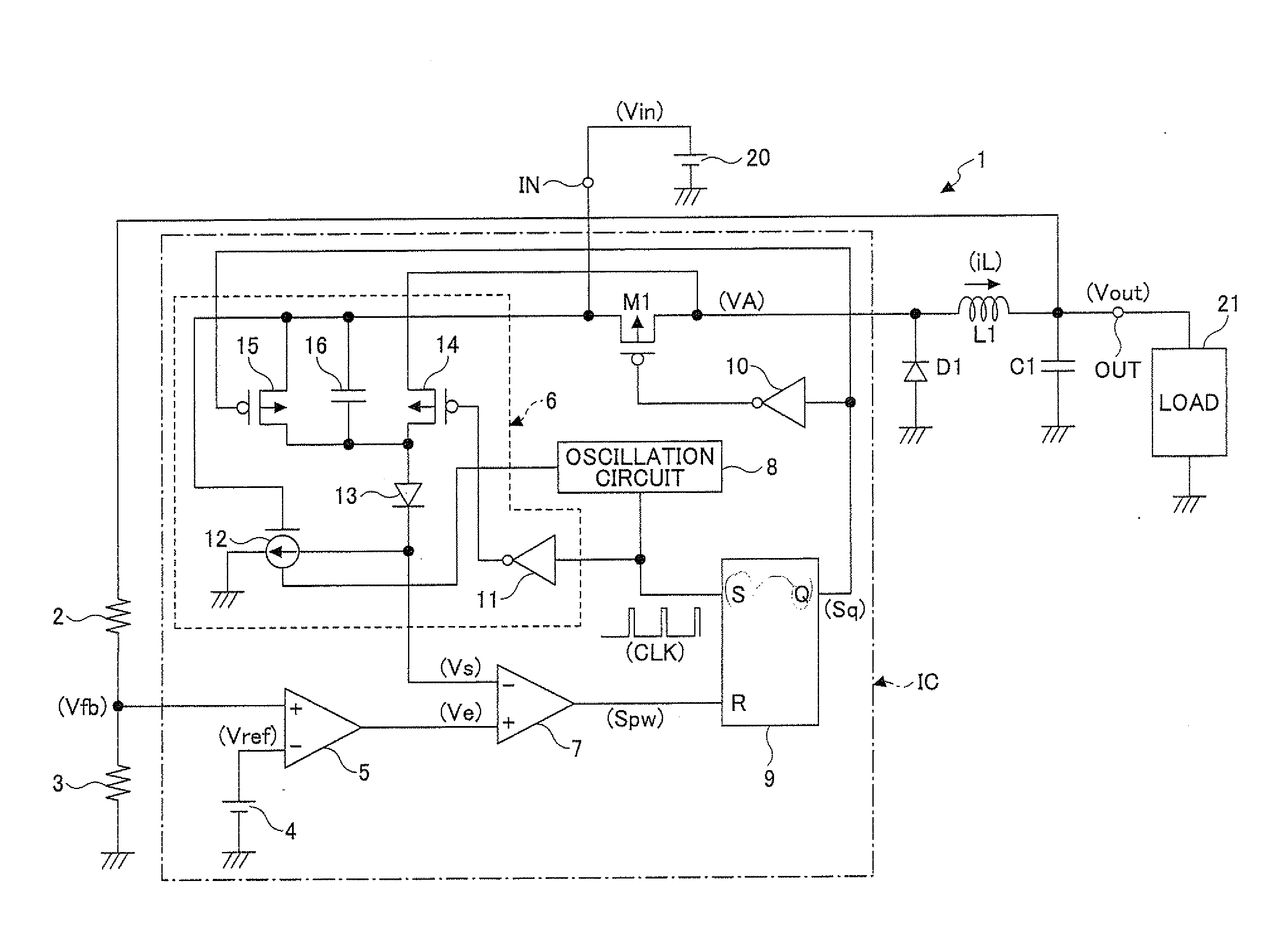
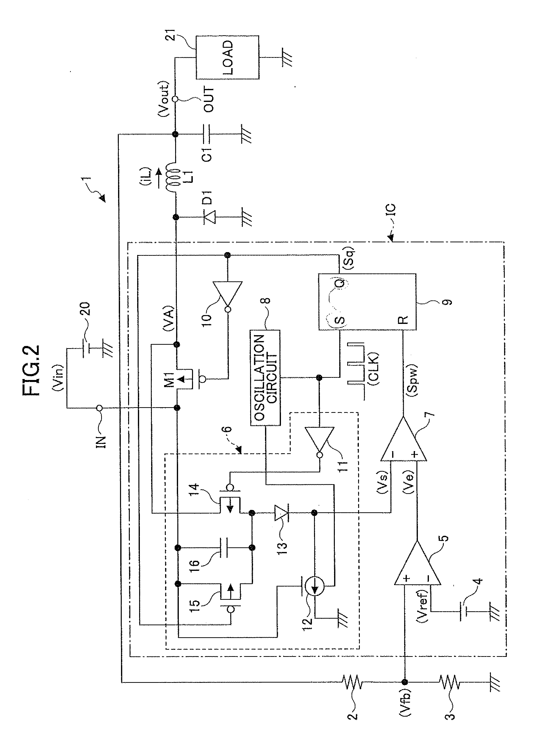
[0032]FIG. 2 is a circuit diagram showing a circuit example of a current-mode control switching regulator according to a first embodiment of the present invention.

[0033]The current-mode control switching regulator (hereinafter referred to as a switching regulator) 1 shown in FIG. 2 constitutes a step-down switching regulator that steps down an input voltage Vin input from a DC power supply 20 to an input terminal IN to a predetermined constant voltage and outputs the stepped input voltage from an output terminal OUT to a load 21 as an output voltage Vout.

[0034]The switching regulator 1 has a switching transistor M1 that is composed of a PMOS transistor for controlling the output of a current from the input terminal IN; a rectifying diode D1; an inductor L1; a smoothing capacitor C1; and output voltage detecting resistors 2 and 3 that divide the output voltage Vout and generate and output a divided voltage Vfb. In addition, the switching regulator 1 has a reference voltage generation...

second embodiment

[0071]Although the first embodiment describes the step-down switching regulator as an example, the present invention can also be applied to a step-up switching regulator, which is described as a second embodiment below.

[0072]FIG. 5 is a circuit diagram showing a circuit example of a current-mode control switching regulator according to the second embodiment of the present invention. Note that in FIG. 5, parts the same as or similar to those of FIG. 2 are denoted by the same reference numerals.

[0073]The switching regulator 1a shown in FIG. 5 constitutes the step-up switching regulator that converts an input voltage Vin input from a DC power supply 20 to an input terminal IN to a predetermined constant voltage and outputs the stepped input voltage from an output terminal OUT to a load 21 as an output voltage Vout.

[0074]The switching regulator 1a has a switching transistor M11 that is composed of a NMOS transistor; a rectifying diode D11; an inductor L1; a smoothing capacitor C1; and o...


PUM


Abstract

Disclosed is a current-mode control switching regulator that steps down or steps up an input voltage input to an input terminal to a predetermined constant voltage and outputs the stepped input voltage from an output terminal as an output voltage. The current-mode control switching regulator includes a switching element, an inductor, a rectifying element, an error amplification circuit unit, an oscillation circuit unit with variable oscillation frequency, a slope voltage generation circuit unit, and a switching control circuit unit.

Description

TECHNICAL FIELD[0001]The present invention relates to a current-mode control switching regulator that operates in a wide input / output voltage range and a wide frequency range.BACKGROUND ART[0002]In general, voltage-mode control switching regulators have been widely used. The voltage-mode control switching regulators perform PWM control on a switching element in accordance with a voltage difference between an output voltage and a reference voltage, thereby stabilizing the output voltage. However, since the voltage-mode control switching regulators detect a returned signal from the output voltage, their response speed to fluctuation in the output voltage is slow and the phase compensation of an error amplification circuit which amplifies the voltage difference between the output voltage and the reference voltage becomes complicated.[0003]As a technology to solve these deficiencies, current-mode control switching regulators have been used in many cases. However, it is known that, when ...

Claims


Application Information

Patent Timeline
Patent Type & Authority Applications(United States)
IPC IPC(8): G05F1/00
CPCH02M3/156
Inventor SOHMA, SHOHTAROH
Owner NISSHINBO MICRO DEVICES INC
Learn More