
Time labelling associated with an equipment synchronisation system connected to a network

a synchronisation system and time labelling technology, applied in the field of time labelling associated with an equipment synchronisation system connected to a network, can solve the problems of single sample not enabling the determination of timestamps without, introduces a strong jitter in the transmission of signals, and fluctuations in the length of time required for information, so as to facilitate the development process and ease the effect of the invention

Inactive Publication Date: 2011-02-17
MAGNOLIA LICENSING LLC
View PDF6 Cites 5 Cited by
  • Summary
  • Abstract
  • Description
  • Claims
  • Application Information

AI Technical Summary

Benefits of technology

"The present invention proposes to adapt a video synchronization device to ensure that devices connected to the same network can determine the current timestamp. This is achieved by extracting image ticks from a synchronization signal, initializing an image counter, and sampling the counting ramp to create a sample PCR. The sample PCR is then inserted into transmitted packets, which are received and processed to regenerate the counting ramp and initialize an image counter. The invention allows for a time labelling function to be realized without significantly increasing data traffic on the network."

Problems solved by technology

A known disadvantage presented by an IP / Ethernet network is that it introduces a strong jitter in a transmission of signals, and particularly for the transmission of a synchronisation signal.
When such a signal is routed by an IP / Ethernet connection to different items of equipment for synchronising, this jitter results in fluctuations in the length of time required for the information carried by the synchronisation signal to reach the equipment.
An inconvenience of this solution is that it renders dependant the video synchronisation clocks on the clocks of the IEEE1588 layer.
The transmission of a counting ramp sample enables the current timestamp only on the ramp duration to be known precisely, which is restrictive.
The transport of a single sample does not enable a timestamp to be determined without ambiguity at an instant.

Method used


Image

  • Time labelling associated with an equipment synchronisation system connected to a network
  • Time labelling associated with an equipment synchronisation system connected to a network
  • Time labelling associated with an equipment synchronisation system connected to a network

Examples


Embodiment Construction

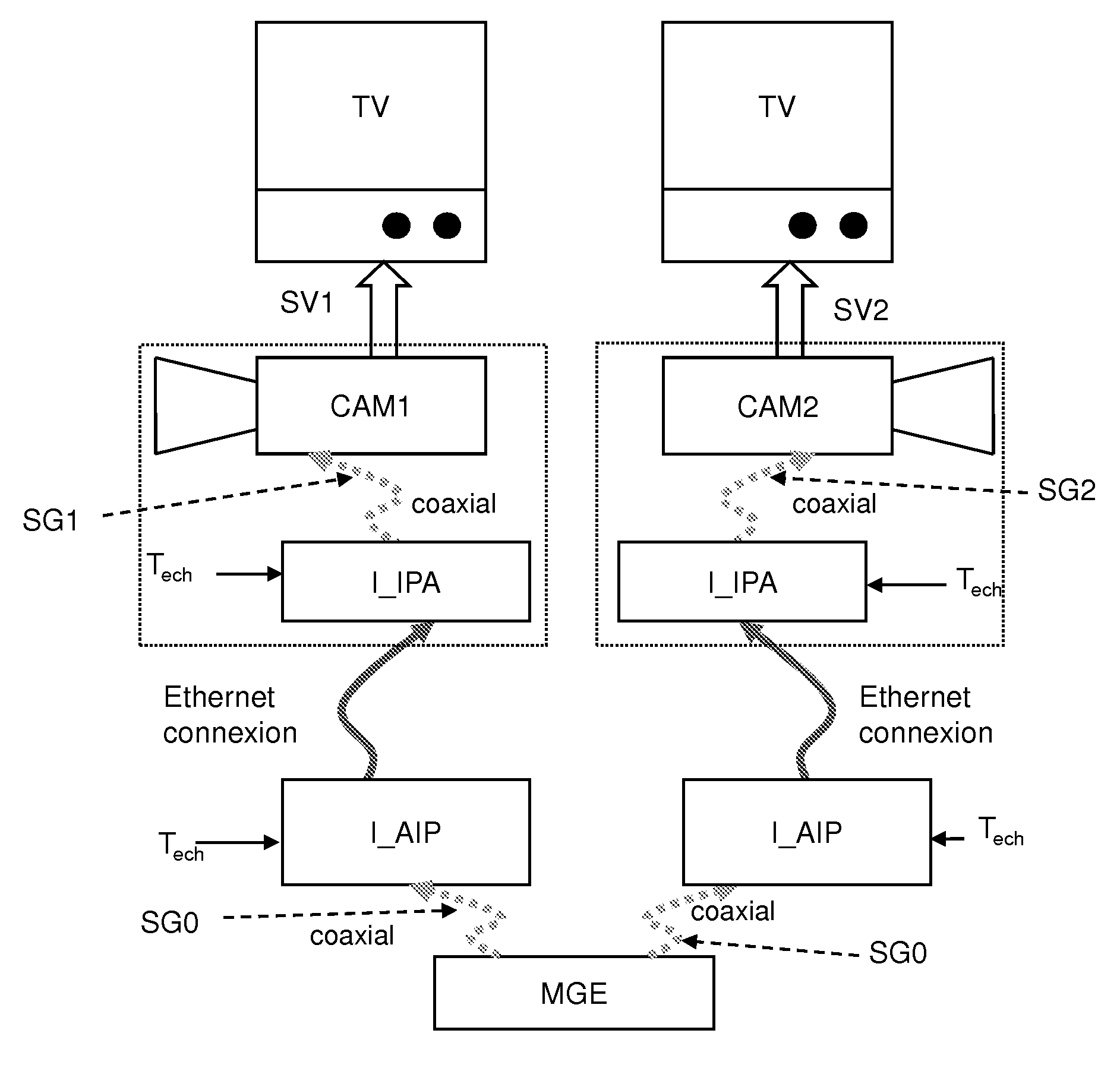
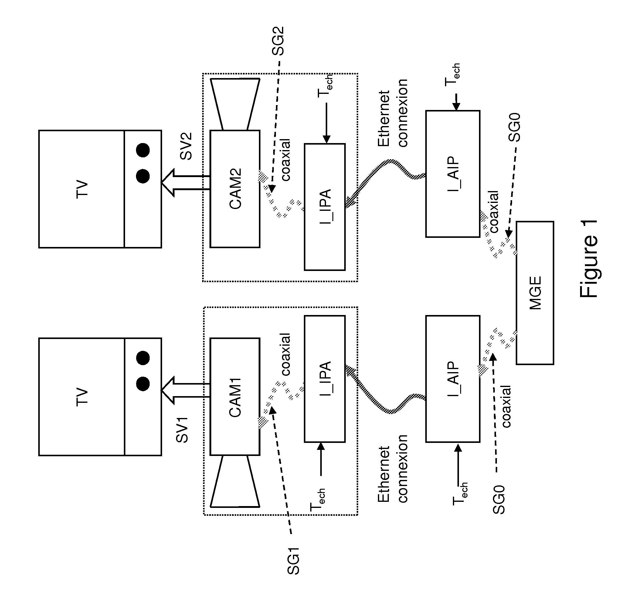
[0044]The current analogue domain is interfaced with the IP / Ethernet network on the transmission side, and the IP / Ethernet network is interfaced with the analogue domain on the reception side, as illustrated in FIG. 1.

[0045]In the same figure, the transmission side comprises a “Genlock master” MGE that is connected to an IP / Analogue interface I_AIP. The Genlock master MGE sends a Genlock signal SG0 to the interfaces I_AIP.

[0046]The reception side is constituted by two cameras (CAM1, CAM2) each connected to an IP / Analogue interface I_IPA. The interfaces I_IPA that will eventually be included in the cameras themselves are responsible for reconstructing the Genlock signals SG1, SG2 intended for cameras CAM1, CAM2. The cameras CAM1, CAM2 each produce a video signal SV1, SV2 that is required to be synchronised perfectly.

[0047]The transmission and reception sides are linked together by a packet switching network that is the source of a jitter occurring in the Genlock signal SG0.

[0048]A sa...


PUM


Abstract

The present invention relates to the domain of video equipment. It concerns more specifically a transmission device able to transmit packets, said device comprising the means to extract image ticks from a synchronisation signal, the means to initialise an image counter from said image ticks, the means to initialise a CPT— PCR counter every “m” passage through zero of the image counter, CPT_PCR producing counting ramps CSE_PCR with a range M, the means to sample the counting ramps CSE_PCR every Tech period, where Tech is from a time base synchronised on all the stations of said network, and the means to transmit packets comprising a PCRe sample of the CSE_PCR counting ramp. According to the invention, it also comprises the means to insert in the packet:—an Num index identifying the CSE_PCR counting ramp from which the PCRe sample is realised, and—a time label Datejnit indicating a CSE_PCR counting ramp timestamp passage through a reference value PCR_REF comprised between 0 and M-1.

Description

SCOPE OF THE INVENTION[0001]The present invention relates to the domain of video equipment.[0002]The present invention relates more particularly to a device for time labelling associated with an equipment synchronisation system connected via a packet switching network, for example of the IP (Internet Protocol) type, whether the network is wired (for example Ethernet (IEEE802.3)) or wireless (for example IEEE 802.16 D-2004).PRIOR ART[0003]Progress in the ability of IP networks to transport all types of signal (data or video) has made it possible to use these networks as the “backbone” architecture for video studios. Of capital importance to this change is therefore having a single infrastructure for the transport of data. Whereas in the past, several media were necessary to transport different signal types between items of equipment, the multiplexing properties offered by the IP layer enable a reduction in the number of media necessary to an IP network that links the different items ...

Claims


Application Information

Patent Timeline
Patent Type & Authority Applications(United States)
IPC IPC(8): H04L12/56H04N7/24
CPCH04N21/23608H04N21/4344H04N21/4305H04N21/242
Inventor TAPIE, THIERRYDEFRANCE, SERGEJOUET, PIERRICK
Owner MAGNOLIA LICENSING LLC
Learn More