Brightness enhancing film and film based diffuser for improved illumination uniformity of displays

Inactive Publication Date: 2011-02-17
3M INNOVATIVE PROPERTIES CO
View PDF21 Cites 18 Cited by
  • Summary
  • Abstract
  • Description
  • Claims
  • Application Information

AI Technical Summary

Benefits of technology

[0010]The above summary of the present invention is not intended to describe each illustrated embodiment or every implementa

Problems solved by technology

In addition, the viewing angle requirements for LCD-TVs are generally different from those for LCD monitors and hand-held devices.
Such an illumination profile is not desirable, and so a diffuser plate is typically used to smooth the illumination profile at the back of the LCD device.
The diffuser plate is generally relatively thick and heavy compared to other light management elements between the lamps and the LCD panel.
The separation between the diffuse reflector and the diffuser is limited by the desired brightness uniformity of the light emitted from the diffuser.
If the separation is too small, then the illuminance becomes less uniform, thus spoiling the image viewed by the viewer.
This comes about because there is insufficient space for the light to spread uniformly between the lamps.

Method used


Image

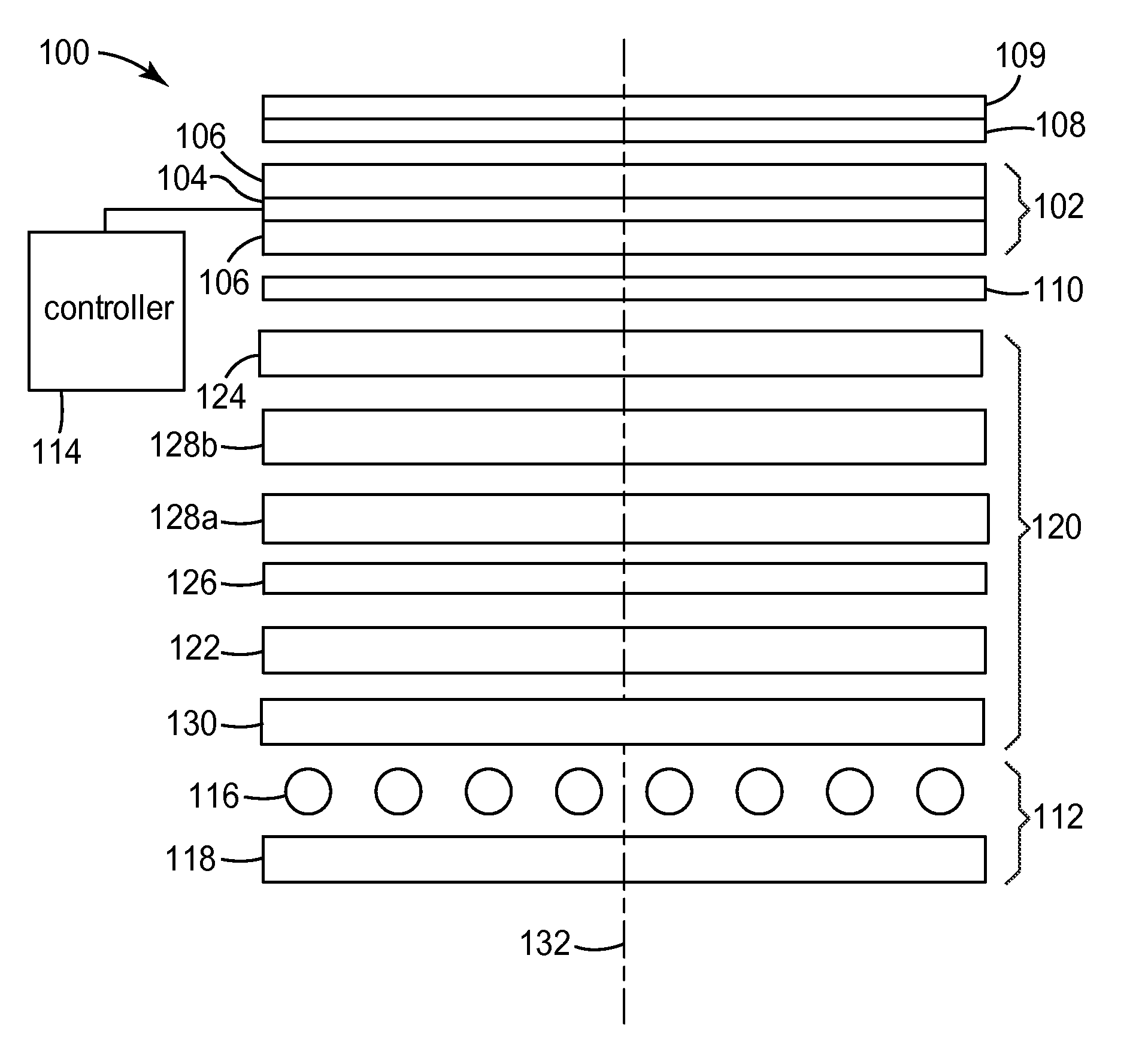
  • Brightness enhancing film and film based diffuser for improved illumination uniformity of displays
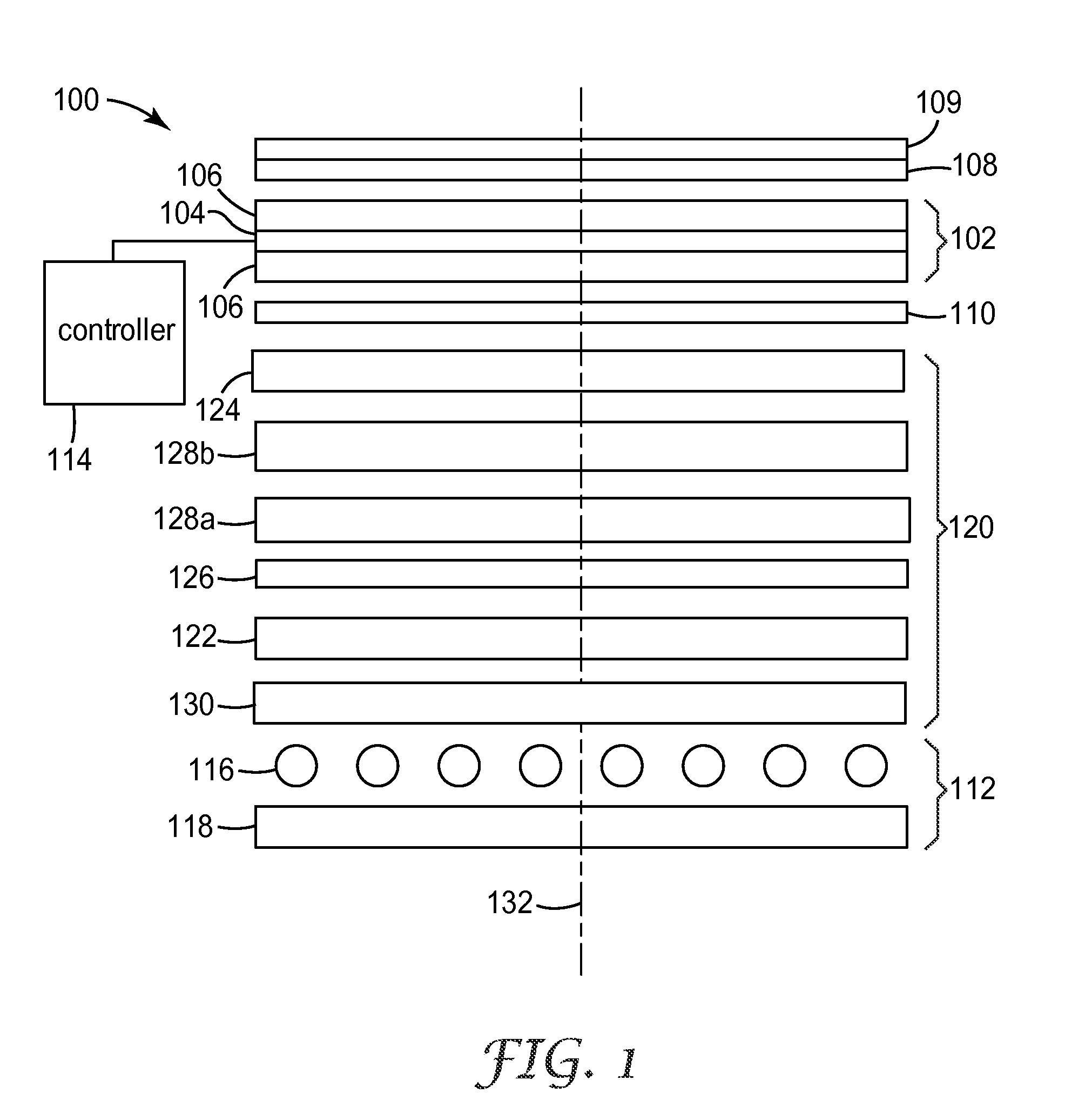
  • Brightness enhancing film and film based diffuser for improved illumination uniformity of displays
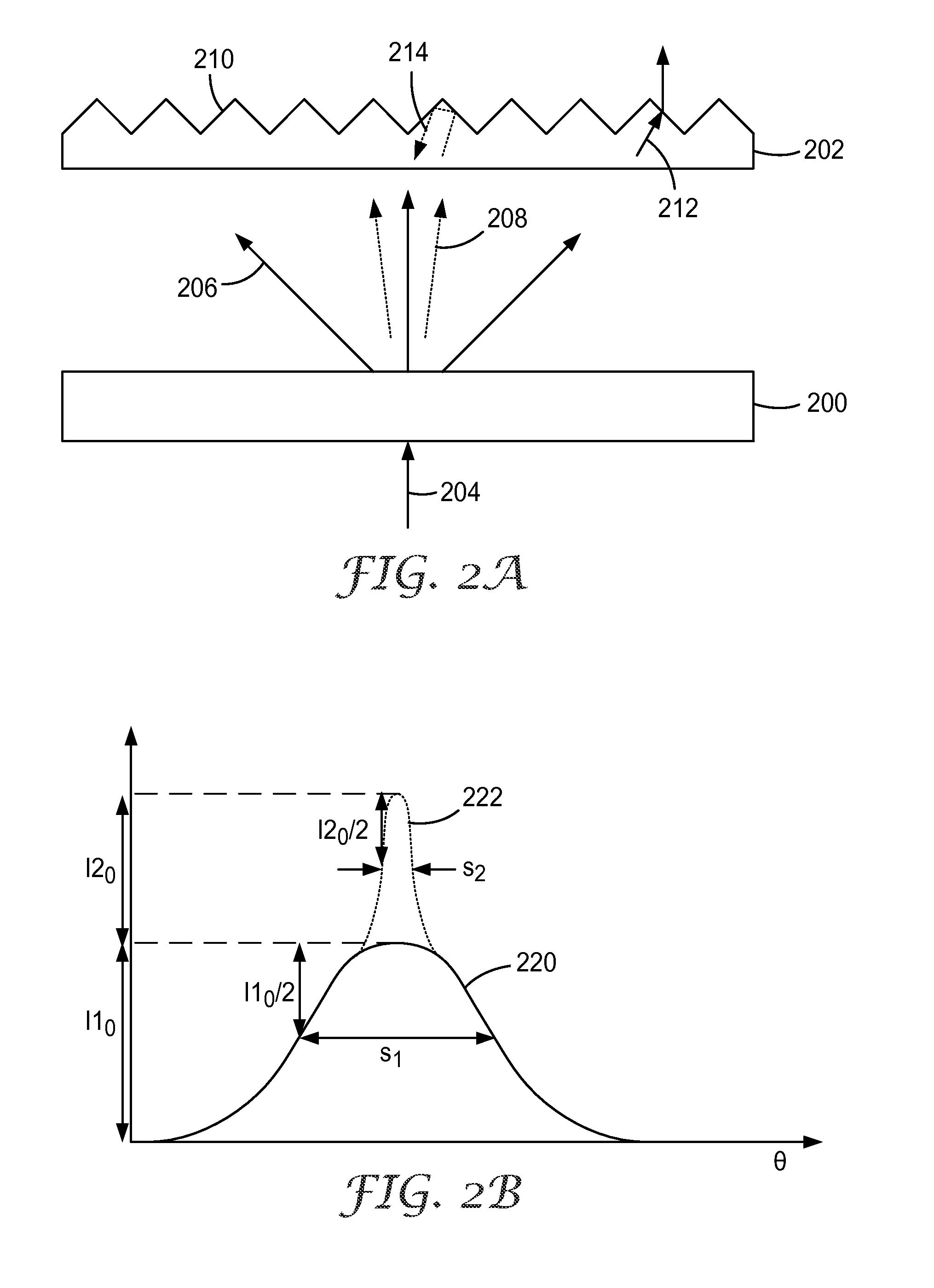
  • Brightness enhancing film and film based diffuser for improved illumination uniformity of displays

Examples


example 1

Punch-Through Diffuser and Reflective Polarizer

[0088]The first modeled example is discussed with reference to FIGS. 8A-8C. The model backlight 800 is based on a diffuser 802 with a reflective polarizer 804 above the diffuser. The lamps 806 had a center to center spacing of S=35 mm and the separation between the rear reflector 808 and the diffuser 802 was 20 mm. FIG. 8B shows the calculated luminance as a function of position across the backlight 800 for increasing values of Upoly, which relates to increasing concentrations of polystyrene bead in the diffuser 800. The assumed value of Utitania, was 33 mm−1. The Upoly values for the different curves are listed in Table III. Curve 832 shows the luminance of a standard diffusing plate having a single pass transmission of 65%.

TABLE IIIUpoly values for Example 1UpolyFIG. 8B - curve no.FIG. 8C - curve no.082084010842208228443084640824848508506082685280828854100830856

[0089]FIG. 8C shows the luminance uniformity as a function of D (mm) for t...

example 2

Punch-Through Diffuser with Brightness Enhancement and Reflective Polarizer

[0091]The second modeled example is discussed with reference to FIGS. 9A and 9B. The model backlight 900 was based on a backlight having a punch-through diffuser 902, a reflective polarizer 904 and a brightness enhancement film 910. The brightness enhancement film 910 was modeled as a prismatic film having uniformly high prismatic ribs on a 50 μm pitch with a 90° apex angle. Lamps 906 were placed above a rear reflector 908. The lamps 906 had a center to center spacing of S=35 mm and the separation between the rear reflector 908 and the diffuser 902 was 20 mm.

[0092]FIG. 9B shows the calculated luminance uniformity as a function of cavity depth, D, for various values of Upoly, which relates to increasing concentrations of polystyrene beads in the diffuser 902. The assumed value of Utitania was 33 mm−1. The Upoly values for the different curves are listed in Table VI.

TABLE IVUpoly values for Example 2UpolyFIG. 9...

example 3

Punch-Through Diffuser with Reflective Polarizer, Brightness Enhancement and EUF

[0094]The third modeled example is discussed with reference to FIGS. 10A-10C. The model backlight 1000, schematically illustrated in FIG. 10A was based on a backlight having a punch through diffuser 1002, a reflective polarizer 1004 and a brightness enhancement film 1010. Lamps 1006 were placed above a rear reflector 1008. The lamps 1006 had a center to center spacing of S=35 mm and the separation between the rear reflector 1008 and the diffuser 1002 was 20 mm. A sheet of EUF 1012 was placed below the punch-through diffuser 1002, and a 2 mm thick clear plate 1014 was placed below the EUF 1012.

[0095]The EUF 1012 was shaped with ribs on a 50 μm pitch, without any spaces between the ribs. Different rib designs were used, as shown in FIG. 10B. The ribs were truncated prisms, similar in shape to those illustrated in FIG. 6B. The sides of the ribs were sloped at different angles, represented by the angle, w, b...


PUM


Abstract

An optical device has a first film (200) that has a first side and a second side. When illuminated by light (204) at the first side, the first film is characterized by a first fraction of broadly diffused transmitted light (206) and a second fraction of narrowly diffused transmitted light (208). A second film (202) is disposed to the second side of the first film. The second film has at least one free surface that diverts light. In some embodiments, the first film has a diffuse scattering optical density between 0.5 and 3. The device finds use in spreading and making light uniform in a backlight in a display such as a liquid crystal display.

Description

RELATED APPLICATIONS[0001]This application claims the benefit of U.S. Provisional Patent Application No. 61 / 029,071, filed on Feb. 15, 2008, the disclosure of which is incorporated by reference herein in its entirety.FIELD OF THE INVENTION[0002]The invention relates to optical displays, and more particularly to liquid crystal displays (LCDs) that are directly illuminated by light sources from behind, such as may be used in LCD monitors and LCD televisions.BACKGROUND[0003]Some display systems, for example liquid crystal displays (LCDs), are illuminated from behind. Such displays find widespread application in many devices such as laptop computers, hand-held calculators, digital watches, televisions and the like. Some backlit displays include a light source that is located to the side of the display, with a light guide positioned to guide the light from the light source to the back of the display panel. Other backlit displays, for example some LCD monitors and LCD televisions (LCD-TVs...

Claims


Application Information

Patent Timeline
IPC IPC(8): G09G3/36G02B5/02G09G5/00
CPCG02B5/021G02B5/0242G02B5/0278G02F2001/133507G02F1/133606G02F1/133611G02B5/045G02F1/133507
Inventor EPSTEIN, KENNETH A.ETZKORN, STEPHAN J.NELSON, ERIC W.GEHLSEN, MARK D.KOETHE, BRIAN G.
Owner 3M INNOVATIVE PROPERTIES CO
Why Eureka
Try Eureka