
Composite magnetic material and method of manufacturing the same

a magnetic material and composite technology, applied in the field of composite materials, can solve the problems of deterioration of strength, inability to provide actual use, and deterioration of magnetic permeability, so as to reduce the amount of resin, improve formability, and improve the effect of formability

Inactive Publication Date: 2011-02-03
TOHO ZINC
View PDF8 Cites 48 Cited by
  • Summary
  • Abstract
  • Description
  • Claims
  • Application Information

AI Technical Summary

Benefits of technology

[0015]The present invention has been invented to solve the above-mentioned problems, and the object of the present invention is to provide a composite magnetic material that is excellent in magnetic properties such as magnetic permeability and core loss, and has practical strength, and a method for manufacturing a composite magnetic material that can improve compactibility of a dust core and reduce manufacturing cost.MEANS TO SOLVE A PROBLEM
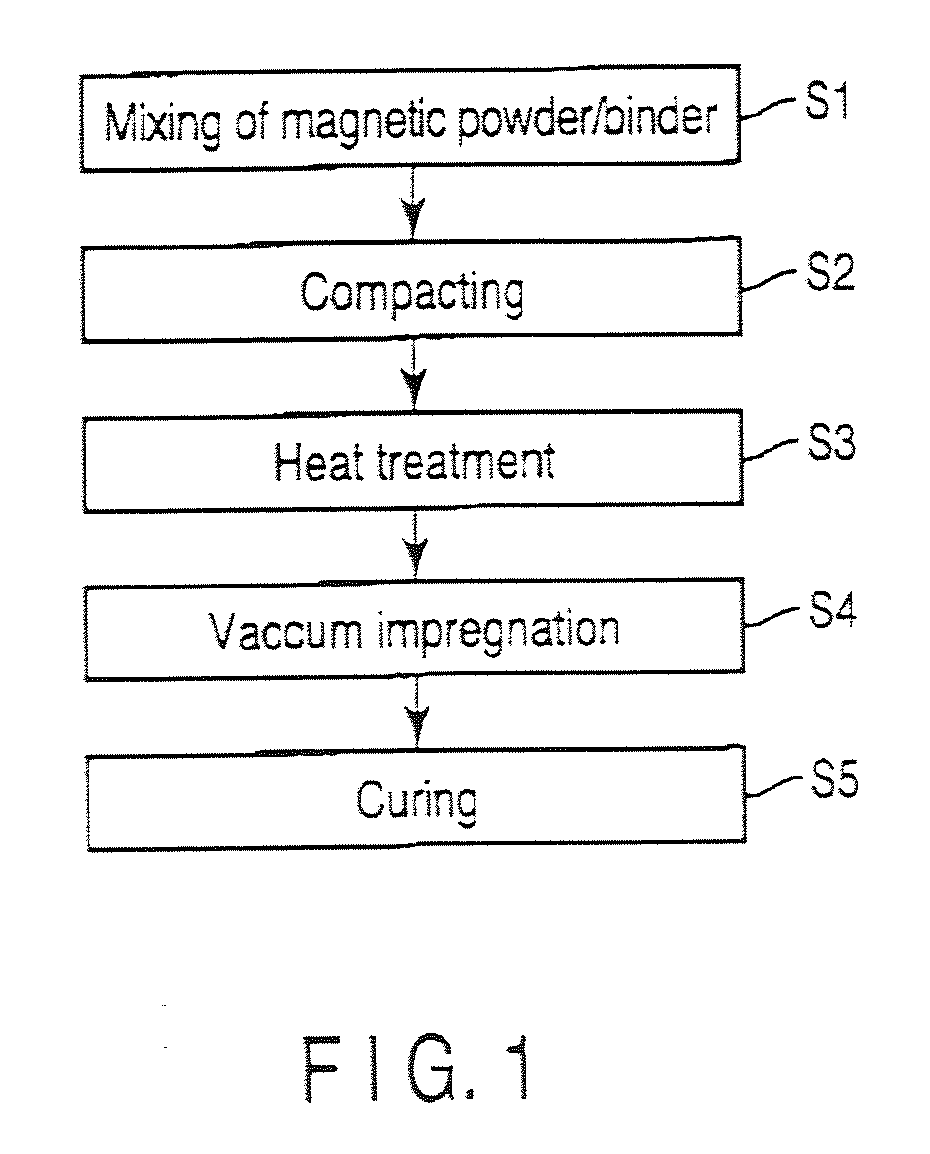
[0017]In a conventional manufacturing method, amorphous powder of a soft magnetic metal and ceramics such as silicone resin or water glass are mixed, dried and then subjected to die-compacting, to obtain a compact of the product shape, and then the strain at the time of the compacting resulting from the amorphous powder is further eliminated, whereby to express various properties of a magnetic body (magnetic permeability, core loss, mechanical strength and the like).
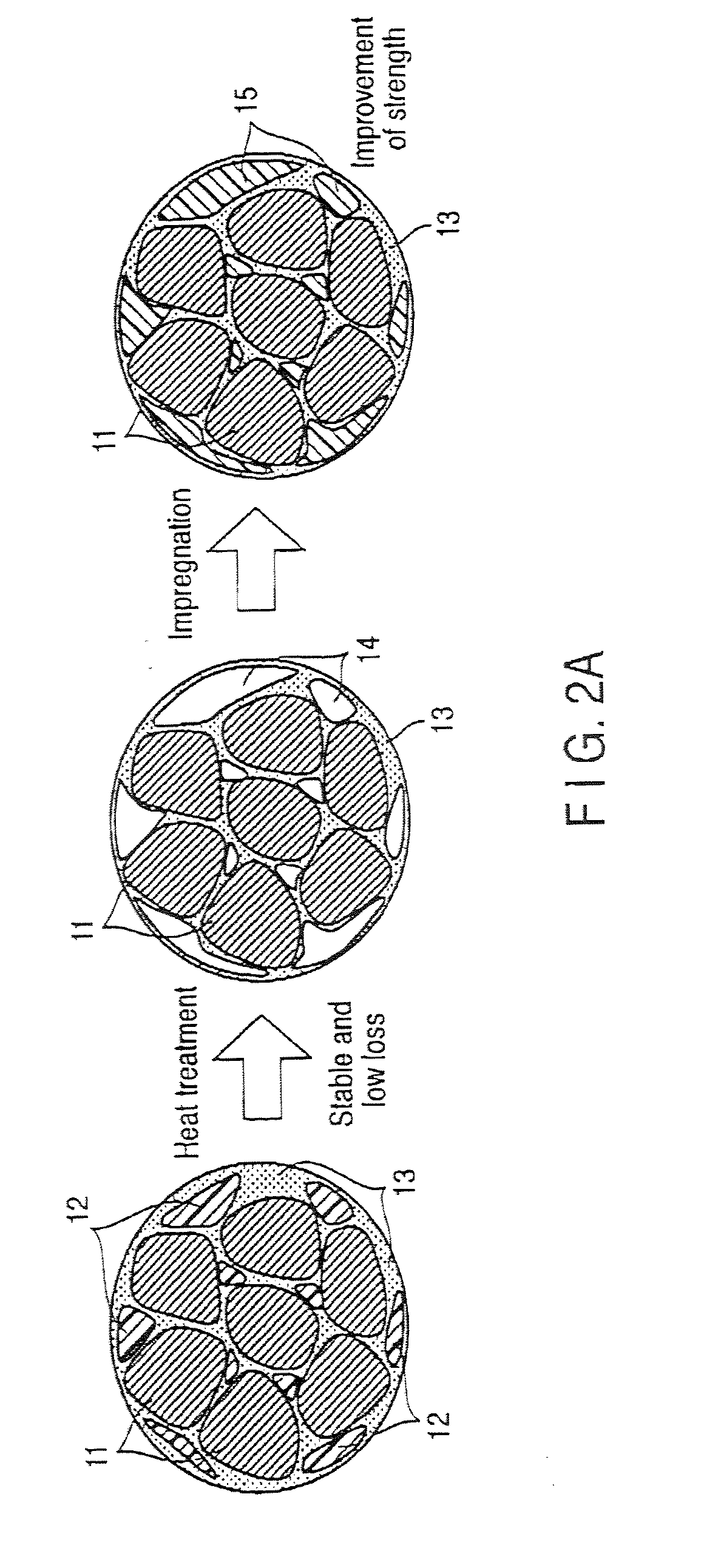
[0025]Furthermore, when amorphous powders are used as the soft magnetic alloy powder, heat treatment at a lower temperature than the crystallization temperature makes it possible to obtain effects of preventing crystallization of the amorphous phase, and further also securing mechanical strength of the compact.
[0030]Furthermore, in the present invention, the resin impregnation step is added after the heat treatment in addition to the steps before the heat treatment, i.e., the (a) mixing step and the (b) compacting step, with the (c) heat treatment step as a border. In other words, by adding the (d) resin impregnation step after the (c) heat treatment stem, it is possible to secure both of bond strength and insulation of magnetic powders by the second binder impregnation resin) even if the first binder (compacting additive) contained in the compact is damaged with the heat treatment step.

Problems solved by technology

However, if the manufacturing method that has been applied to these crystalline soft magnetic metal powder, is applied to an amorphous soft magnetic metal powder, there is a problem such that the strength becomes deteriorated and providing to actual use is impossible.
Furthermore, if the strength is improved within the range of the conventional manufacturing method described in the Non-Patent Document 1, reversely, the core loss property causes deterioration of the magnetic permeability and decrease of the performance in comparison with the case where crystalline soft magnetic metal powder is used.
However, with this method, distortion due to contraction of the coating film generated in the course of solidification of the coating material after the coating, deteriorates the performance of the magnetic body.
Therefore, the surface coating method is neither effective means for solving the problems.
As described above, the conventional methods have a problem of not effectively using basic properties of amorphous powder.
And a dust core using-such powder has insufficient strength, and thus is difficult to provide for actual use.
The reason is that the dust core has bad compactibility, and easily has breakage or crack at the time of a compacting step, and thus has low manufacture yield ratio, and in fact has higher manufacturing cost than the ferrite.
For example, with the conventional method of Patent Document 3, if amorphous alloy powder is used as atomized powder in the compacting step, it causes various problems such that a mixture of the amorphous alloy powder and the silicone resin has poor flowability, which leads to no increase of the compacting speed; the powder is sandwiched between the die and the punch, which leads to breakage of the die and the punch and accordingly to lowering of capacity utilization; failure of the compact occurs leading to low yield ratio; and further arbitrary property of the compact shape exhibited in the ferrite is not secured.
Due to such poor compactibility, the dust core is min to ferrite at any time, which is a main cause to the minor position in the competition.

Method used


Image

  • Composite magnetic material and method of manufacturing the same
  • Composite magnetic material and method of manufacturing the same
  • Composite magnetic material and method of manufacturing the same

Examples


examples

[0090]Hereinafter, various embodiments and Examples of the present invention will be explained by illustrative embodiments.

first embodiment

[0091]As the first embodiment of the present invention, a Fe alloy having a rough composition of 9.6% Si and 5.5% Al obtained by a vacuum dissolution method was manufactured, and sieve-isolated with control of powder treatment step conditions by mechanical pulverization, to manufacture alloy powder having different sphericities. 0.04 of the first binder (the compacting additive) by the mass ratio was added to the alloy powder, and the mixture was wet-mixed using methylethyl ketone and granulated while being heat-dried, to obtain mixed powders. The silicone resin and the organic resin were blended as the first binder in a ratio of silicone resin:organic resin=1:1.

[0092]0.012 of zinc stearate by the mass ratio was further added and mixed to the mixed powders, and the mixture was compacted into a product shape having 21 mm of the outer diameter, 12 mm of the inner diameter and 7 mm of the height at about 1.5 GPa pressure using a mechanical compacting machine. This compact was placed in...

second embodiment

[0102]Crystalline powder of a Fe—Si—Al alloy was manufactured in the same manner as in the first embodiment. When the content of Si and Al was small, pulverization with usual mechanical pulverization method was difficult, and thus any powder was manufactured with the water atomization method. Using these powders, Sample 5 (Comparative Example 3) was manufactured by the conventional method, and Sample 6 (Example 3) was manufactured by the method of the present invention. The strength of each of Samples 5 and 6 was measured. Table 3 shows the Si and Al contents of the manufactured alloys by % by mass.

TABLE 3SampleClassificationNo.ItemMeasured valueComparative5Composition3%Si,6.5%Al,8%Si,10%Si,8%Si,9%Si,Example 30%Al0%Al1%Al4%Al6%Al5%AlStrength16.49.77.73.95.64.3(MN / m2)Example 36Composition3%Si,6.5%Al,8%Si,10%Si,8%Si,9%Si,0%Al0%Al1%Al4%Al6%Al5%AlStrength554938413634(MN / m2)

[0103]From Table 3, it was shown that the strength of Sample 6 of Example 3 was higher than that of Sample 5 of Com...


PUM

PropertyMeasurementUnit
Fractionaaaaaaaaaa
Fractionaaaaaaaaaa
Percent by massaaaaaaaaaa

Abstract

Certain embodiments provide a composite magnetic material for an inductor, wherein a non-magnetic material contains a first binder as a compacting additive, and is added to and mixed with the soft magnetic metal powder, and a second binder that is impregnated to a compact as a binder after the heat treatment of the compact obtained by adding the first binder to the soft magnetic metal powder and compacting it, and the soft magnetic metal powder contains 40% by mass or more (including 100%) of spherical particles of which the ratio L2 / L1 between a perimeter L1 of a particle cross-section in the two dimensional plane view and a perimeter L2 of a circle having equivalent cross-sectional area is 0.5 or more.

Description

CROSS REFERENCE TO RELATED APPLICATIONS[0001]This is a Continuation Application of PCT Application No. PCT / JP2009 / 057450, filed Apr. 13, 2009, which was published under PCT Article 21(2) in Japanese.[0002]This application is based upon and claims the benefit of priority from prior Japanese Patent Applications No. 2009-106046, filed Apr. 15, 2008; and No. 2008-106047, filed Apr. 15, 2008, the entire contents of both of which are incorporated herein by reference.BACKGROUND OF THE INVENTION[0003]1. Field of the Invention[0004]The present invention relates to an inductor that is wire-wound to a metal-based soft magnetic composite material that is applied to an electronic circuit such as a power circuit, particularly a composite magnetic material such as a dust core material used as a core that is excellent in magnetic properties, and a method for manufacturing the same.[0005]2. Description of the Related Art[0006]In recent years, along with needs for miniaturization and power-saving of ...

Claims


Application Information

Patent Timeline
IPC IPC(8): H01F1/06B22F7/04B22F1/08B22F1/10
CPCB22F1/0059B22F3/26B22F2998/10C22C2202/02H01F1/15375H01F1/26H01F1/15333H01F41/0246B22F3/02B22F3/10B22F1/10B22F1/08
Inventor OTSUKI, ETSUOKANEDA, AYAKO
Owner TOHO ZINC
Learn More