
Self-contained counterpoise compound loop antenna

a self-contained, compound antenna technology, applied in the direction of individual energised antenna arrays, loop antennas with ferromagnetic cores, resonant antennas, etc., can solve the problems of low received power than would otherwise be possible, not typically suitable for transmitters, and small loop antennas that cannot be used in practi

Active Publication Date: 2011-01-27
DOCKON
View PDF12 Cites 78 Cited by
  • Summary
  • Abstract
  • Description
  • Claims
  • Application Information

AI Technical Summary

Benefits of technology

[0002]Embodiments of the present invention relate to a self-contained counterpoise compound field antenna. Improvements relate particularly, but not exclusively, to compound loop antennas having coplanar electric field radiators and magnetic loops with electric fields orthogonal to magnetic fields that achieve performance benefits in higher bandwidth (lower Q), greater radiation intensity / power / gain, and greater efficiency. Embodiments of the self-contained antenna include a transition formed on the magnetic loop and having a transition width greater than the width of the magnetic loop. The transition substantially isolates a counterpoise formed on the magnetic loop opposite or adjacent to the electric field radiator.STATEMENTS AS TO THE RIGHTS TO INVENTIONS MADE UNDER FEDERALLY SPONSORED RESEARCH OR DEVELOPMENT

Problems solved by technology

Known antennas in devices such as mobile / cellular telephones provide one of the major limitations in performance and are almost always a compromise in one way or another.
When operating as a receiver, the sub-optimal performance of the antenna results in lower received power than would otherwise be possible.
As such they are not typically suitable as transmitters.
This physical constraint tends to mean that very small loop antennas cannot be used in practice.
One of the limitations of ELS antennas mentioned by Wheeler and Chu, which is of particular importance, is that they have large radiation quality factors, Q, in that they store, on time average more energy than they radiate.
According to Wheeler and Chu, ELS antennas have high radiation Q, which results in the smallest resistive loss in the antenna or matching network and leads to very low radiation efficiencies, typically between 1-50%.
As a result, since the 1940's, it has generally been accepted by the science world that ELS antennas have narrow bandwidths and poor radiation efficiencies.
Many of the modern day achievements in wireless communications systems utilizing ELS antennas have come about from rigorous experimentation and optimization of modulation schemes and on air protocols, but the ELS antennas utilized commercially today still reflect the narrow bandwidth, low efficiency attributes that Wheeler and Chu first established.
Compound field antennas have proven to be complex and difficult to physically implement, due to the unwanted effects of element coupling and the related difficulty in designing a low loss passive network to combine the electric and magnetic radiators.
The Shiga antenna further requires an expensive semiconductor substrate.
While it is known to print some lower frequency devices on an inexpensive glass reinforced epoxy laminate sheet, such as FR-4, which is commonly used for ordinary printed circuit boards, the dielectric losses in FR-4 are considered to be too high and the dielectric constant not sufficiently tightly controlled for such substrates to be used at microwave frequencies.
In addition, none of these planar antennas are compound loop antennas.
Real power leaves the source and never returns, whereas the imaginary or reactive power tends to oscillate about a fixed position (within a half wavelength) of the source and interacts with the source, thereby affecting the antenna's operation.

Method used


Image

  • Self-contained counterpoise compound loop antenna
  • Self-contained counterpoise compound loop antenna
  • Self-contained counterpoise compound loop antenna

Examples


Embodiment Construction

[0040]Embodiments provide an improved planar, compound loop (CPL) antenna, capable of operating in both transmit and receive modes and enabling greater performance than known loop antennas. The two primary components of a CPL antenna are a magnetic loop that generates a magnetic field (H field) and an electric field radiator that emits an electric field (E field).

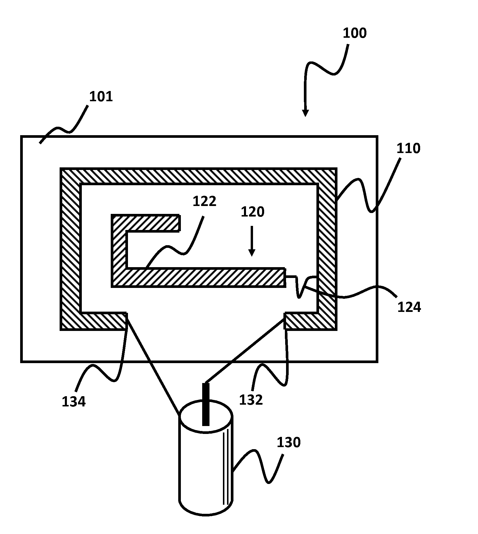
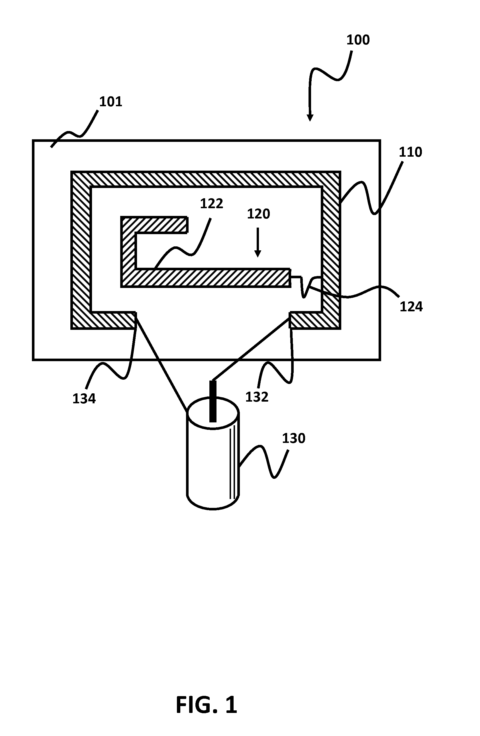
[0041]The electric field radiator may be physically located either inside the loop or outside the loop. For example, FIG. 1 shows an embodiment of a single CPL antenna element with the electric field radiator located on the inside of the loop coupled by an electrical trace, while FIGS. 3A and 3B show two embodiments of a single CPL antenna element with the electric field radiator located on the outside of the loop. FIG. 3A, as further described below, includes a phase tracker for broadband applications, while FIG. 3B does not include the phase tracker and is more suitable for less wideband applications. FIGS. 4A, 4B and 4C ...


PUM


Abstract

The present invention relates to a self-contained counterpoise compound field antenna. Improvements relate particularly, but not exclusively, to compound loop antennas having coplanar electric field radiators and magnetic loops with electric fields orthogonal to magnetic fields that achieve performance benefits in higher bandwidth (lower Q), greater radiation intensity / power / gain, and greater efficiency. Embodiments of the self-contained antenna include a transition formed on the magnetic loop and having a transition width greater than the width of the magnetic loop. The transition substantially isolates a counterpoise formed on the magnetic loop opposite or adjacent the electric field radiator.

Description

CROSS-REFERENCES TO RELATED APPLICATIONS[0001]This application is a Continuation in Part of National Stage Ser. No. 12 / 921,124, filed Sep. 3, 2010, which claims priority to Patent Cooperation Treaty Serial Number PCT / GB2009 / 050296, filed Mar. 26, 2009, which claims priority to Patent Application Serial Number GB0805393.6, filed Mar. 26, 2008. This application is a non-provisional application taking priority from U.S. Provisional Application No. 61 / 303,594, filed Feb. 11, 2010.BRIEF DESCRIPTION OF THE INVENTION[0002]Embodiments of the present invention relate to a self-contained counterpoise compound field antenna. Improvements relate particularly, but not exclusively, to compound loop antennas having coplanar electric field radiators and magnetic loops with electric fields orthogonal to magnetic fields that achieve performance benefits in higher bandwidth (lower Q), greater radiation intensity / power / gain, and greater efficiency. Embodiments of the self-contained antenna include a tr...

Claims


Application Information

Patent Timeline
Patent Type & Authority Applications(United States)
IPC IPC(8): H01Q7/00
CPCH01Q7/00H01Q9/30H01Q9/40H01Q21/30H01Q21/08H01Q21/28H01Q9/42
Inventor BROWN, FORREST JAMES
Owner DOCKON
Learn More