
Production method for a surface sensor, system and use of a surface sensor

Inactive Publication Date: 2011-01-27
DRITTE PATENTPORTFOLIO BET GMBH & CO KG
View PDF5 Cites 20 Cited by
  • Summary
  • Abstract
  • Description
  • Claims
  • Application Information

AI Technical Summary

Benefits of technology

[0061]The releasing of the THz structure from the substrate may be accomplished for example by undercutting. Doing so thus largely prevents an overly strong precharging of the THz structure by the substrate and simultaneously achieves a field magnification at the edge. This leads to the THz structure being particularly sensitive—and that independent of a precharging by the substrate—to an applied thin layer to be detected. In other words, a capture molecule at an edge provided with a strong field magnification proves to be particularly sensitive to the detection of molecules—and that at resonance characteristics that are largely independent of the substrate.
[0062]In a particularly preferred further development, the THz structure is passivated except on one edge in such a manner that binding of a capture molecule is suppressed or prevented relative the edge. This has the further advantage that the capture molecules only bind in the immediate area of the edge, since a field interaction can only take place in this area due to the passivation of the remaining area. The releasing of the edge thus offers a simple way to achieve a location-selective binding of capture molecules.
[0063]For this purpose, the passivation can advantageously be realized in the form of a passivation layer. The THz structure can advantageously be formed as a metallic structure. The metallic surface may be covered for example with a non-precious metallic or an electrically insulating passivation layer which suppresses or prevents the chemical binding of the capture molecules.

Problems solved by technology

Although extremely interesting in the economical and technical respect, none of these methods have hitherto been able to prevail over the established label-based method.
This polarization dependency poses a problem for the technical application, since each misadjustment could erroneously be interpreted as a sensor response—hence there is a high cross-sensitivity.
FSS having completely symmetrical resonator elements such as those of the initially cited articles, do not have this polarization dependency when at a sufficiently low enough spacing, but in this case also lack the necessary resonance indifference required to achieve a sufficiently high enough sensor sensitivity.

Method used


Image

  • Production method for a surface sensor, system and use of a surface sensor
  • Production method for a surface sensor, system and use of a surface sensor
  • Production method for a surface sensor, system and use of a surface sensor

Examples


first embodiment

[0081]FIG. 3 shows a surface sensor 100 in which a THz structure 1 in the form of a metal layer 5 is applied to a substrate 6 in the form of a dielectric material in the usual manner.

[0082]In a further development of this first embodiment, a second embodiment of a surface sensor 200 shown in more detail in FIG. 4 may be realized, in which a part of the substrate 6 is removed. Thereby, an edge, in the present case a slot edge 8 of the metal layer 5, is released relative the substrate 6 in a particularly advantageous manner. This can be advantageously achieved by undercutting the metal layer 5 in the area of the edge.

[0083]The releasing of the edge 8 enables the resonance characteristics of the THz resonance structure 1 to be determined largely independent of the substrate. Moreover, a field magnification forms in the area of the edge which makes the THz resonance structure 1 in this important area thereof sensitive with respect to deposited molecules or the like to be detected.

second embodiment

[0084]FIG. 7 shows a third further embodiment of a modified THz structure 300 as compared to the second embodiment illustrated in FIG. 4. For the remainder, identical reference numerals have been used here for identical or similar features, respectively features having the same or an identical function.

[0085]In extension of the second embodiment, the metal layer 5 in the surface sensor 300 is covered by a non-precious metallic passivation layer 9 which suppresses or prevents chemical binding of the capture molecules. In the present case, the passivation layer 9 is applied to the metal layer 5 prior to the undercutting to release the slot edge 8. The passivation layer 9 in the form of a non-precious metallic layer is hence removed by being etched away together with the not further described metal layer 5 for forming the THz structure on the substrate 6 in regions 7 outside the THz structure, with the slot edge 8 thereby being released at the same time.

[0086]FIG. 8 shows a further mod...

fourth embodiment

[0088]The third as well as FIGS. 7 and 8 ensures that capture molecules as shown in the area 9a will only bind in the immediate area of the undercut slot edge 8 of the metal layer 5. The discussed application of the passivation layer 9, 11 will namely prevent an interaction between the capture molecules and the metal layer 5, respectively will only be possible in the area of the edge 8.

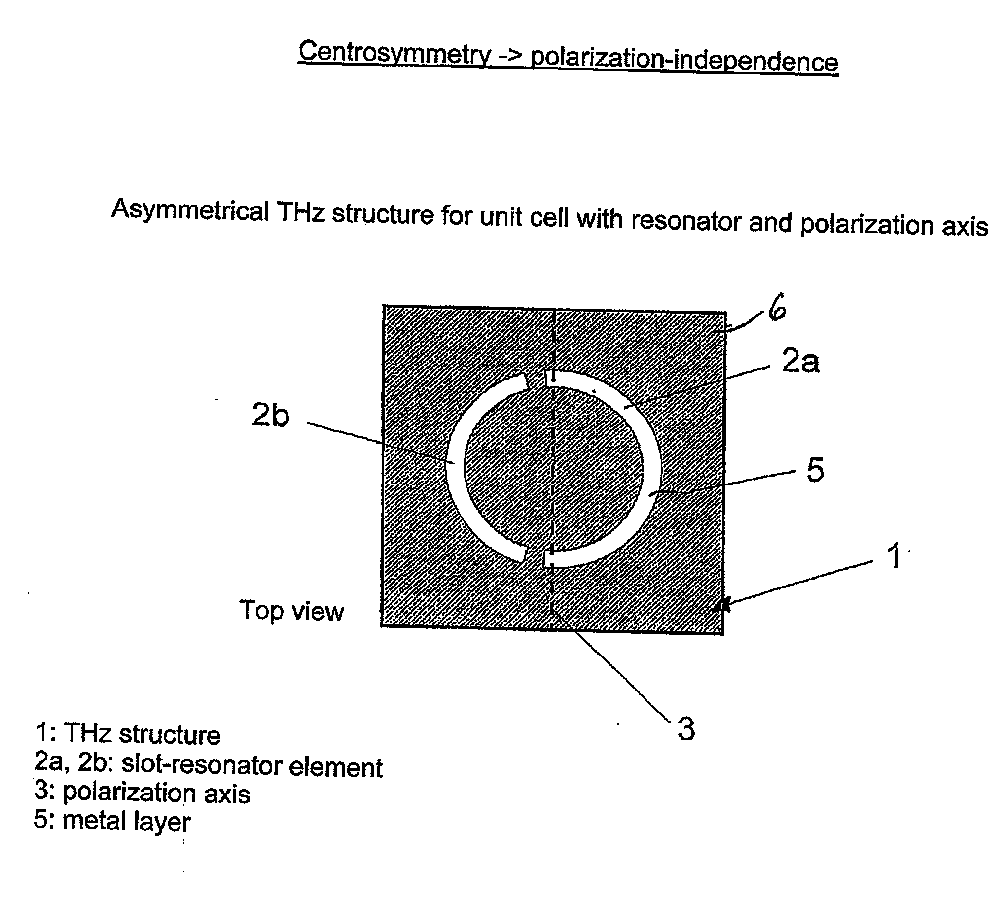
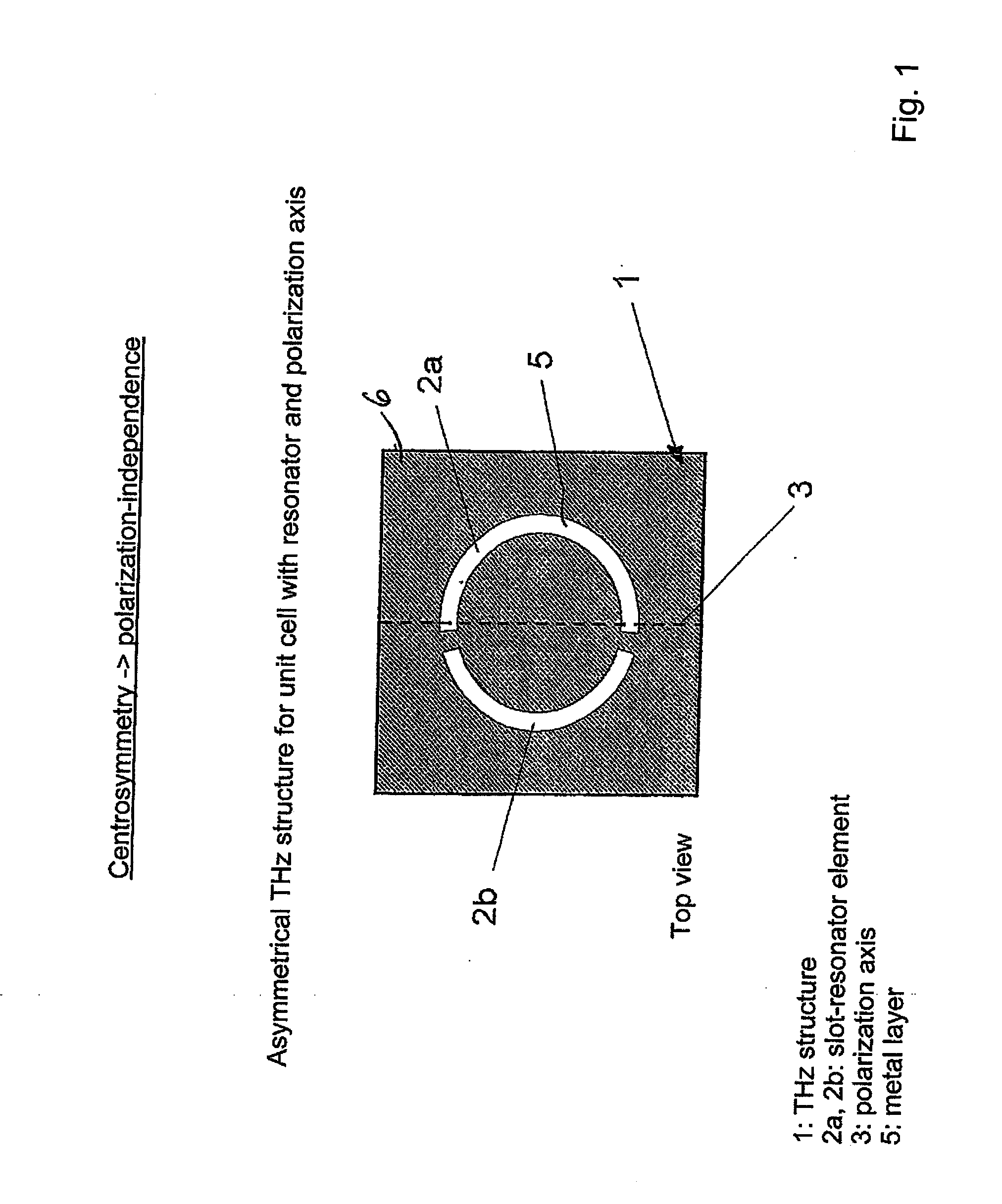
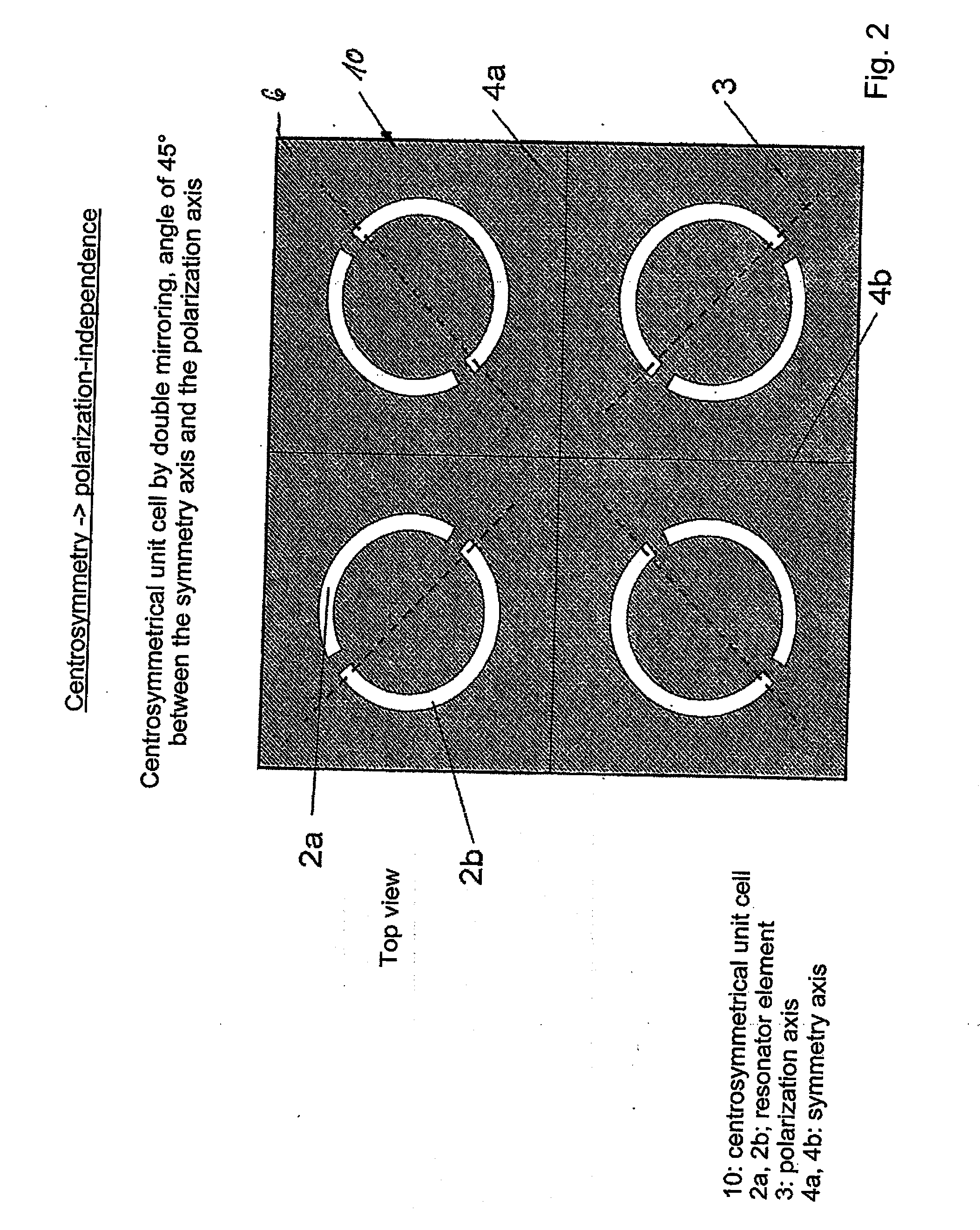
[0089]In summary, the invention relates to a surface sensor 100, 200, 300, 400, comprising a frequency-selective surface with periodically arranged THz structures 1 sensitive to THz radiation, in particular THz resonator structures 1, each having an associated polarization axis 3. In order to improve remote field characteristics, the invention provides for the asymmetrical configuration of a THz structure 1, and a group of two or more THz structures to have essentially centrosymmetrically aligned polarization axes for forming a unit cell.


PUM


Abstract

The invention relates to a surface sensor (100, 200), comprising a frequency-selective surface with periodically arranged THz structures (1), in particular THz resonance structures (1) which are sensitive to THz radiation, a polarization axis (3) being associated with each structure. In order to improve remote field characteristics, the invention provides for a THz structure (1) to be configured asymmetrically, and a group of two or more THz structures (1) to have essentially centrosymmetrically aligned polarization axes (3) for forming a unit cell.

Description

CROSS-REFERENCE TO RELATED APPLICATIONS[0001]This application is a Section 371 of International Application No. PCT / EP2009 / 053376, filed Mar. 23, 2009, which was published in the German language on Oct. 1, 2009, under International Publication No. WO 2009 / 118287 A8 and the disclosure of which is incorporated herein by reference.BACKGROUND OF THE INVENTION[0002]The invention relates to a surface sensor, comprising a frequency-selective surface with periodically arranged THz structures sensitive to terahertz radiation (THz radiation), in particular THz resonator structures each having an associated polarization axis. The invention further relates to a method of producing a surface sensor. The invention moreover relates to a system having a surface sensor, as well as a use of the surface sensor.[0003]Periodic antenna structures in the microwave range or other electromagnetically active periodic structures are known, for example, from US 2007 / 011431 A1 or US 2006 / 0152430 A1. A THz measu...

Claims


Application Information

Patent Timeline
IPC IPC(8): H01L27/14B05D5/12
CPCG01N21/3563G01N21/3581G07D7/06
Inventor NAGEL, MICHAEL
Owner DRITTE PATENTPORTFOLIO BET GMBH & CO KG
Learn More