
Production of chemically functionalized nano graphene materials

a technology of nano graphene and functionalized materials, which is applied in the direction of chemical/physical/physical-chemical processes, energy-based chemical/physical/physical-chemical processes, organic chemistry, etc., can solve the problems of high cost of moderately priced multi-walled cnts, inability to meet the requirements of high-volume polymer composites and other functional applications, and inability to meet the requirements of large-scale production

Active Publication Date: 2011-01-27
GLOBAL GRAPHENE GRP INC
View PDF5 Cites 105 Cited by
  • Summary
  • Abstract
  • Description
  • Claims
  • Application Information

AI Technical Summary

Benefits of technology

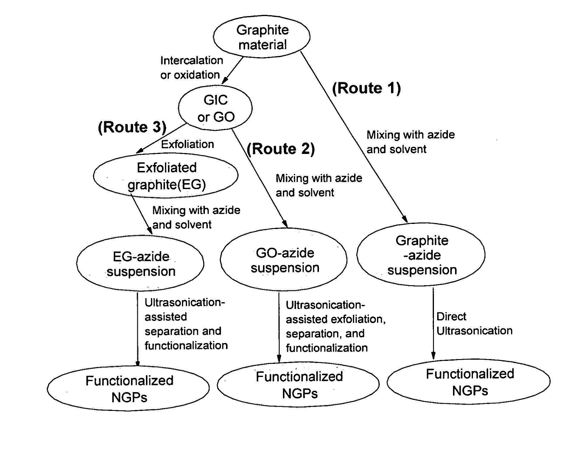
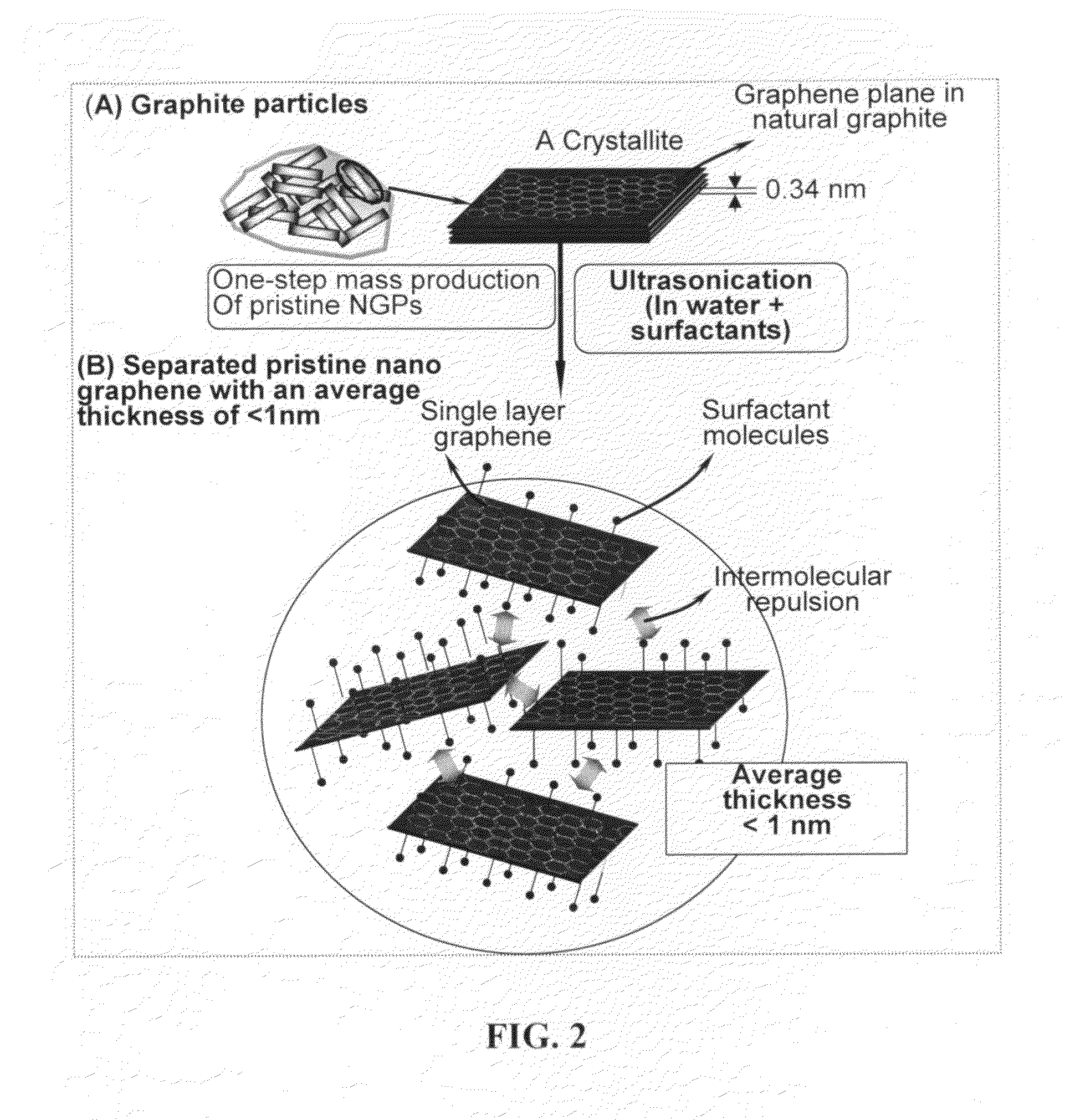
[0021]As a first preferred embodiment, the present invention provides a highly innovative, “combined production-functionalization process” for manufacturing a chemically functionalized nano graphene material directly from a pristine graphite material. The process comprises (A) Dispersing the pristine graphite material and an azide or bi-radical compound in a liquid medium (comprising a solvent if the compound is in a solid state) to form a suspension; and (B) Subjecting the suspension to direct ultrasonication with ultrasonic waves of a desired intensity for a length of time sufficient to produce nano graphene platelets and to enable a chemical reaction to occur between the nano graphene platelets and the azide or bi-radical compound to produce the functionalized nano graphene material. Concurrent production and functionalization of NGPs directly from pristine graphitic materials are achieved.
[0023]In this process, the azide or bi-radical compound may be added to the liquid medium (containing the pristine graphite material) concurrently or sequentially after direct ultrasonication of the graphite material is allowed to proceed for a short period of time. The starting pristine graphite material may be selected from the group consisting of natural graphite, artificial graphite, highly oriented pyrolytic graphite, carbon fiber, graphite fiber, carbon nano-fiber, graphitic nano-fiber, meso-carbon micro-bead, graphitized coke, and combinations thereof.
[0026]The process may further comprise a step of grafting a polymer chain to a functional group of the functionalized nano graphene material to produce a polymer-grafted nano graphene material. This feature enables the design and production of specially grafted NGPs for use as a nano filler for a specific polymer matrix.

Problems solved by technology

However, attempts to produce CNT in large quantities have been fraught with overwhelming challenges due to poor yield and costly fabrication and purification processes.
Additionally, even the moderately priced multi-walled CNTs remain too expensive to be used in high volume polymer composite and other functional applications.
Further, for many applications, processing of nanocomposites with high CNT concentrations has been difficult due to the high melt viscosity.
However, this very difference in geometry also makes electronic structure and related physical and chemical properties very different between NGP and CNT.
There is a misconception in the scientific community that van der Waals forces are weak forces, which needs some qualifications.
However, the magnitude of van der Waals forces drops precipitously when the separation increases just slightly.
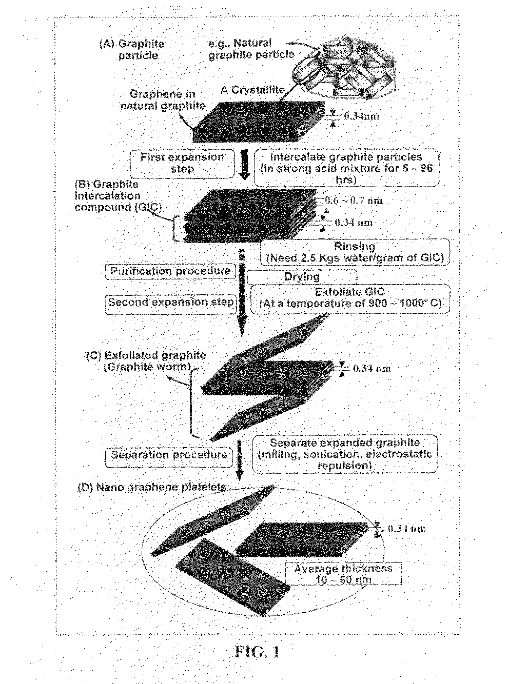
Unfortunately, typically a significant portion of the gaseous molecules escape without contributing to exfoliation of graphite flakes.
Additionally, many of the exfoliated flakes re-stack together by re-forming van der Waals forces if they could not be properly separated in time.
It is important to note that the separation treatment (e.g. using ultrasonication or shearing) is to separate those thick flakes from one another (breaking up the graphite worm or sever those weak interconnections), and it is not intended for further peeling off individual graphene planes.

Method used


Image

  • Production of chemically functionalized nano graphene materials
  • Production of chemically functionalized nano graphene materials
  • Production of chemically functionalized nano graphene materials

Examples


examples

Materials

[0100]Both pristine graphene and graphene oxide materials were obtained from Angstron Materials, LLC (Dayton, Ohio) and the product codes were N002N (pristine) and N002P (graphene oxide). The multi-walled carbon nanotubes (MWNTs) were purchased from (purity >95%). The single-walled carbon nanotubes (SWNTs) were acquired from Shenzhen Nanotech Port Co. (purity of CNTs >90%, purity of SWNTs >50%). Succinic anhydride (98%), stannous octoate ([CH3(CH2)3 CH(C2H5)COO]2Sn, 95%), and ethylene glycol (99%) were purchased from Aldrich and used as received. 2-Bromoisobutyryl bromide (98%), N,N,N′,N″,N″-pentamethyldiethylenetriamine (PMDETA, 99%), N,N-(dimethylamino)pyridine (DMAP, 98%), and boron trifluoride diethyl etherate (BF3.OEt2, 98%) were purchased from Alfa Aesar and used as received. ε-Caprolactone (Acros, 99%) and palmitoyl chloride (Fluke, 97%) were used without further purification. Sodium azide (95%), 2-chloroethanol (99%), 3-chloropropylamine hydrochloride (98%), potassi...


PUM


Abstract

Provided in this invention is a process for producing chemically functionalized nano graphene materials, known as nano graphene platelets (NGPs), graphene nano sheets, or graphene nano ribbons. Subsequently, a polymer can be grafted to a functional group of the resulting functionalized NGPs. In one preferred embodiment, the process comprises (A) dispersing a pristine graphite material and an azide or bi-radical compound in a liquid medium comprising to form a suspension; and (B) subjecting the suspension to direct ultrasonication with to ultrasonic waves of a desired intensity or power level for a length of time sufficient to produce nano graphene platelets and to enable a chemical reaction to occur between the nano graphene platelets and the azide or bi-radical compound to produce the functionalized nano graphene material. Concurrent production and functionalization of NGPs directly from pristine graphitic materials can be achieved in one step and in the same reactor.

Description

[0001]The present invention is a result of a research and development project sponsored by the US National Science Foundation Small Business Technology Transfer (STTR) Program.FIELD OF THE INVENTION[0002]The present invention relates generally to the field of nano graphene platelets (NGPs), also known as graphene nano sheets or graphene nano ribbons. This invention provides methods and processes for chemically functionalizing NGPs, including both pristine NGPs and their oxidized versions (graphite oxide nano platelets). A primary goal of producing chemically functionalized NGPs is improved solubility of NGPs in a liquid medium, improved dispersibility of NGPs in a matrix material, or enhanced interfacial bonding between NGPs and a matrix material in a composite.BACKGROUND OF THE INVENTION[0003]Nanocomposites containing a nano-scaled filler possess unique features and functions unavailable in conventional fiber-reinforced polymers. One major filler development in the past two decades...

Claims


Application Information

Patent Timeline
IPC IPC(8): B01J19/10
CPCB82Y30/00B82Y40/00B01J19/10C01B31/0469C01B31/0484C01B31/0423C01B32/225C01B32/19C01B32/194
Inventor ZHAMU, ARUNAJANG, BOR Z.
Owner GLOBAL GRAPHENE GRP INC
Learn More