Tool holder

a tool and holder technology, applied in the field of tool holders, can solve the problems of inability to finely adjust the pressure force of the taper cone, troublesome coolant supply mechanism, and inability to expand the grinding diameter of the grinding cone, so as to reduce the operation burden of the operator and low cost

Active Publication Date: 2011-01-20
HONDA MOTOR CO LTD
View PDF36 Cites 3 Cited by
  • Summary
  • Abstract
  • Description
  • Claims
  • Application Information

AI Technical Summary

Benefits of technology

[0011]One or more embodiments of the invention provide a low cost tool holder which can carry out multiple honing operations in a general-purpose machine tool, while reducing an operation burden of an operator in each honing operation.

Problems solved by technology

However, since the general-purpose machine tool, in many cases, does not have an oil pressure control function, in order to meet the above request, as a method for adjusting the pressure force of the taper cone, there is necessary a different method from the oil pressure control method.
Therefore, if the supply pressure of the coolant is changed, there can be raised a trouble in the coolant supply mechanism.
Therefore, even when the method of JP-B-07-004759 is applied to a honing operation using the general-purpose machine tool under the above presupposition, it is impossible to finely adjust the pressure force of the taper cone.
As a result, a grinding diameter to be expanded can not be varied so that a given fixed diameter can only be selected.
This raises a problem that a cost of the tool holder is expensive.
This raises a problem that an operator must bear an excessive operation burden.

Method used


Image

  • Tool holder
  • Tool holder
  • Tool holder

Examples


Embodiment Construction

[0026]An exemplary embodiment of the invention is described with reference to the accompanying drawings.

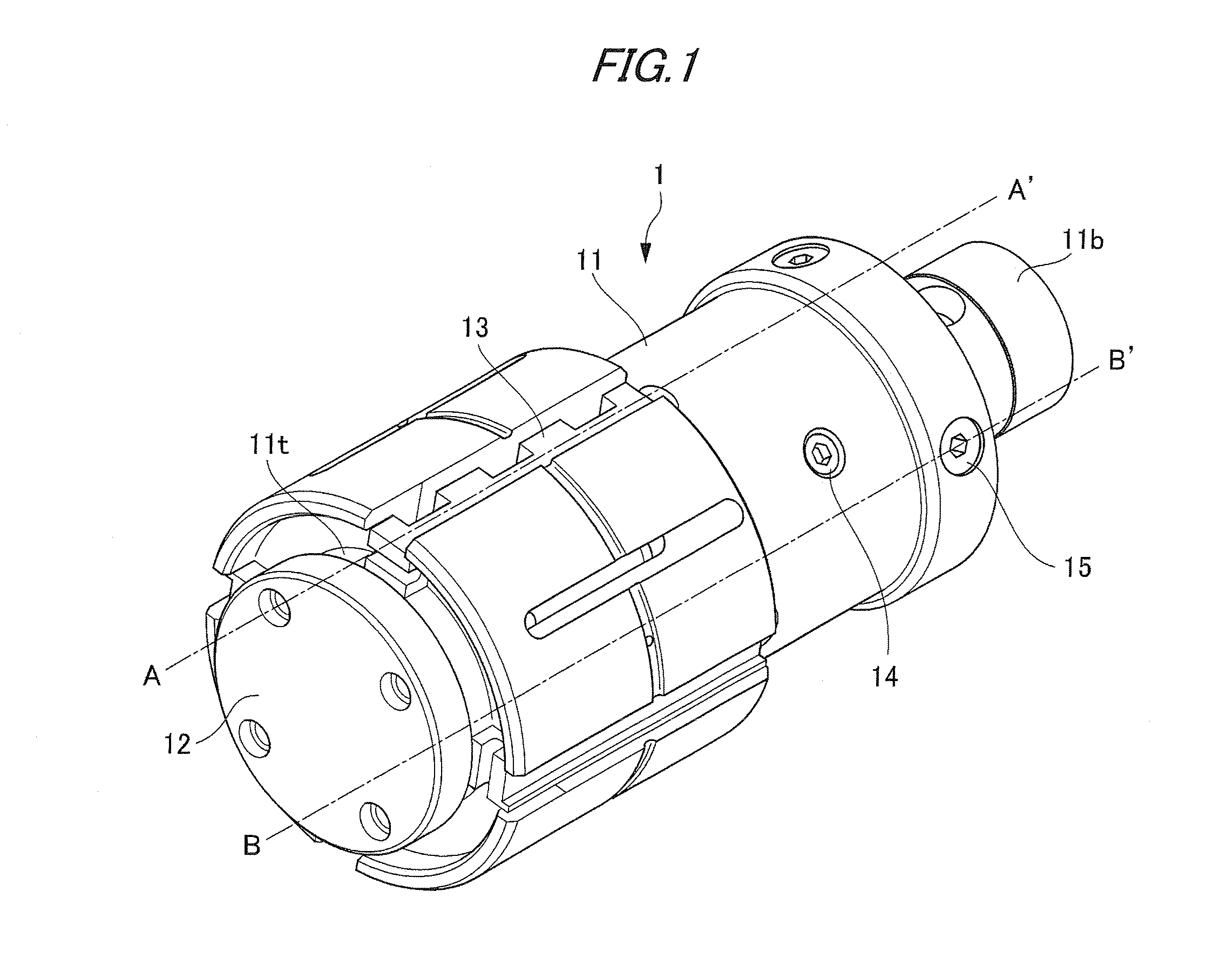
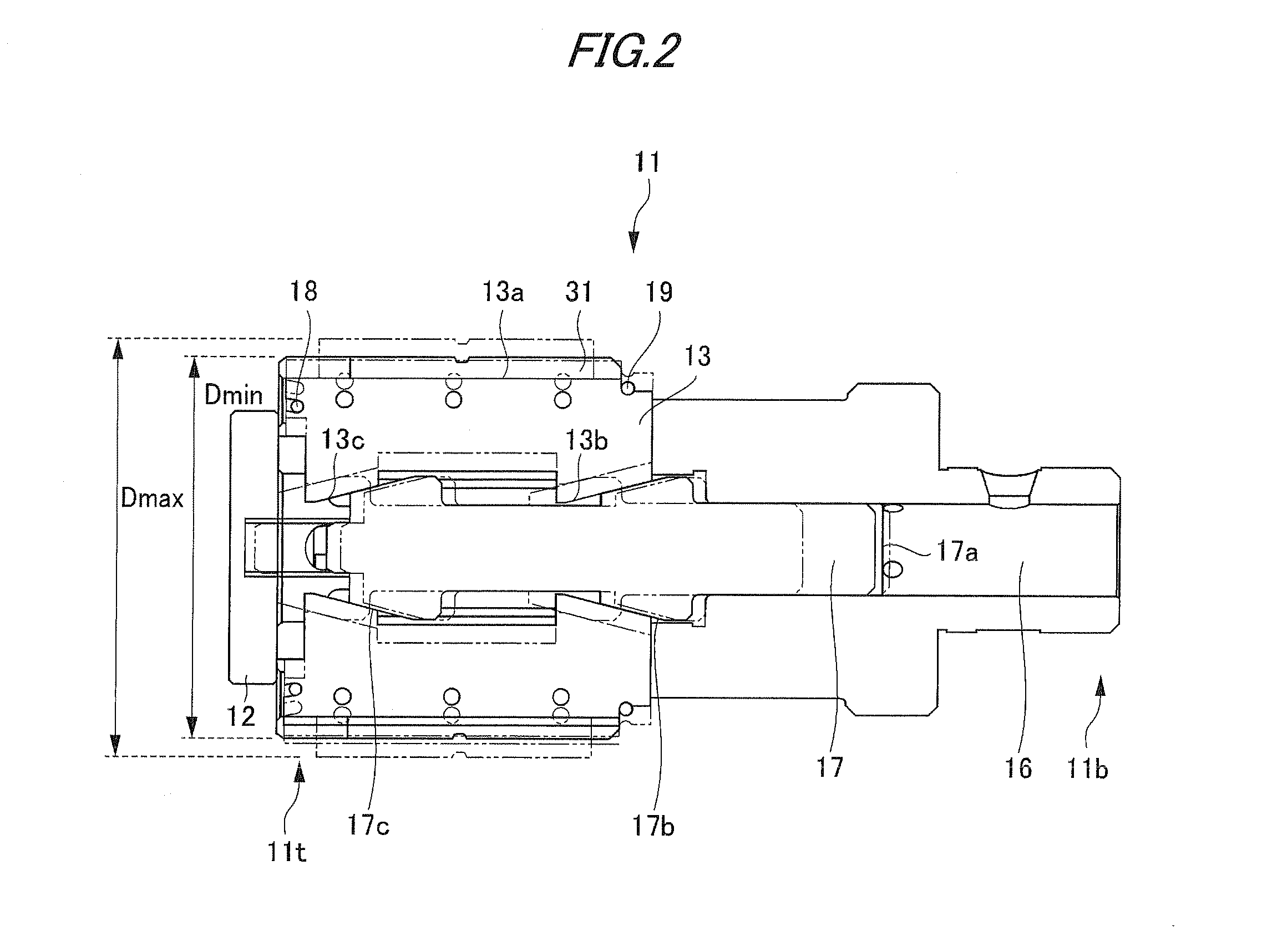
[0027]FIG. 1 is a perspective view to a schematic structure of a honing holder 1 according to an exemplary embodiment of the invention. FIG. 2 is a section view of the honing holder 1, taken along A-A′ line in FIG. 1. FIG. 3 is a section view of the honing holder 1, taken along B-B′ line in FIG. 1.

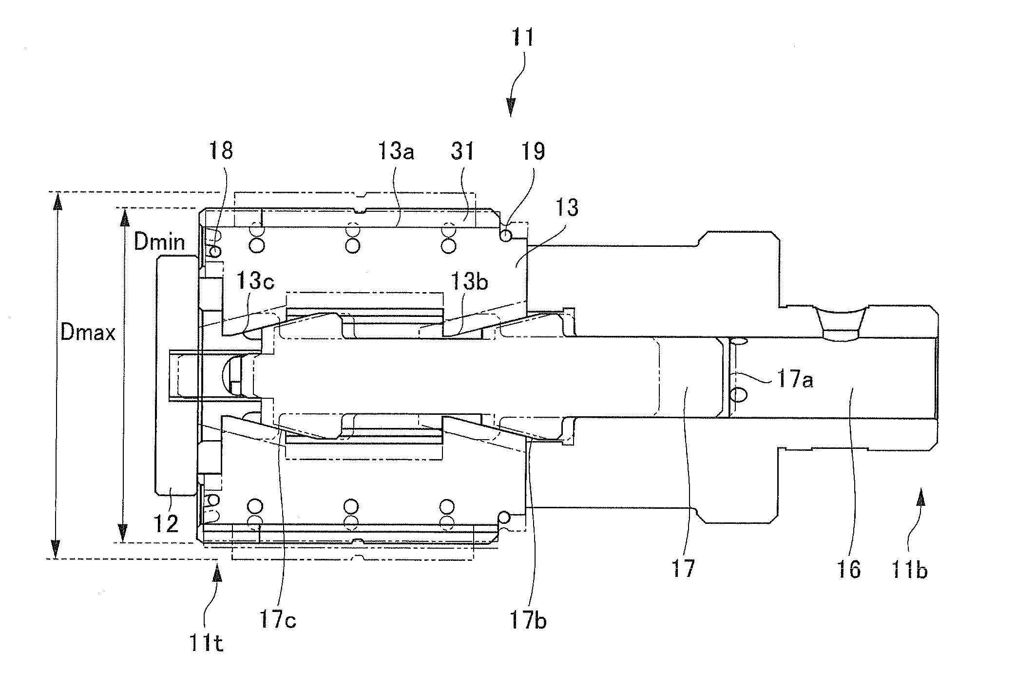
[0028]As shown in FIGS. 1 to 3, the honing holder 1 for use in a honing operation includes a main body 11, an end cap 12, a grinding shoe 13, a fixing screw 14, a screw-like adjuster 15, a coolant flow passage 16, a taper cone 17, springs 18 and 19, and a coolant discharge passage 20.

[0029]The main body 11 includes a leading end portion 11t and a base end portion 11b each having a substantially cylindrical shape. The leading end portion 11t and the base end portions 11b respectively extend in a direction of an axis (a line which extends parallel to the A-A′ line and B-B′ line shown in FI...


PUM

PropertyMeasurementUnit
pressing forceaaaaaaaaaa
diameteraaaaaaaaaa
diametersaaaaaaaaaa

Abstract

A tool holder is provided with a main body, a taper cone, a working portion, a coolant flow passage, and an adjuster. The taper cone includes a taper portion and movable in an axial direction of the main body. The working portion is mounted on an outer peripheral portion of the main body and includes a taper bottom surface which engages with the taper portion. The taper bottom surface is movable in a radial direction of the main body based on a movement of the taper cone in the axial direction. A coolant flows through the coolant flow passage such that a part of the coolant presses and moves the taper cone in the axial direction and another part of the coolant flows out to an outside so as to adjust a pressing force. The adjuster is fitted into a hole penetrating the main body and includes a coolant flow-out hole for adjusting a flow-out of the coolant.

Description

BACKGROUND OF THE INVENTION[0001]1. Field of the Invention[0002]The present invention relates to a tool holder used in a honing operation for grinding and finishing an inner surface of a hole formed in a workpiece with high precision. Specifically, the invention relates to a tool holder which allows a general-purpose machine tool to carry out multiple honing operations.[0003]2. Related Art[0004]Conventionally, a tool holder is used for a honing operation. The tool holder includes, on a leading end portion thereof, grinding shoes with their associated slender grindstones. Hereinafter, such tool holder is referred to as a honing holder. The honing holder, generally, is mounted on a main spindle of a honing machine. In a state where a grindstone is in surface contact with an inner surface of the hole of a workpiece, the honing holder is rotated and simultaneously reciprocated in an axial direction thereof by the honing machine, so as to minutely cut or abrasively finish the inner surfa...

Claims


Application Information

Patent Timeline
Patent Type & Authority Applications(United States)
IPC IPC(8): B24B33/02B24B55/02B24B1/00B24B33/08
CPCB24B33/02B24B55/02B24B33/08
Inventor NORO, DAISUKEKOYAMA, HIROAKISUGAI, KENJIYOSHIKAWA, HIROAKIMITSUYOSE, SATOSHIMIZUHORI, TAKEFUMI
Owner HONDA MOTOR CO LTD
Why Eureka
Try Eureka