
Percutaneous mitral annulplasty with cardiac rhythm management

Inactive Publication Date: 2011-01-13
EDWARDS LIFESCIENCES AG
View PDF100 Cites 57 Cited by
  • Summary
  • Abstract
  • Description
  • Claims
  • Application Information

AI Technical Summary

Benefits of technology

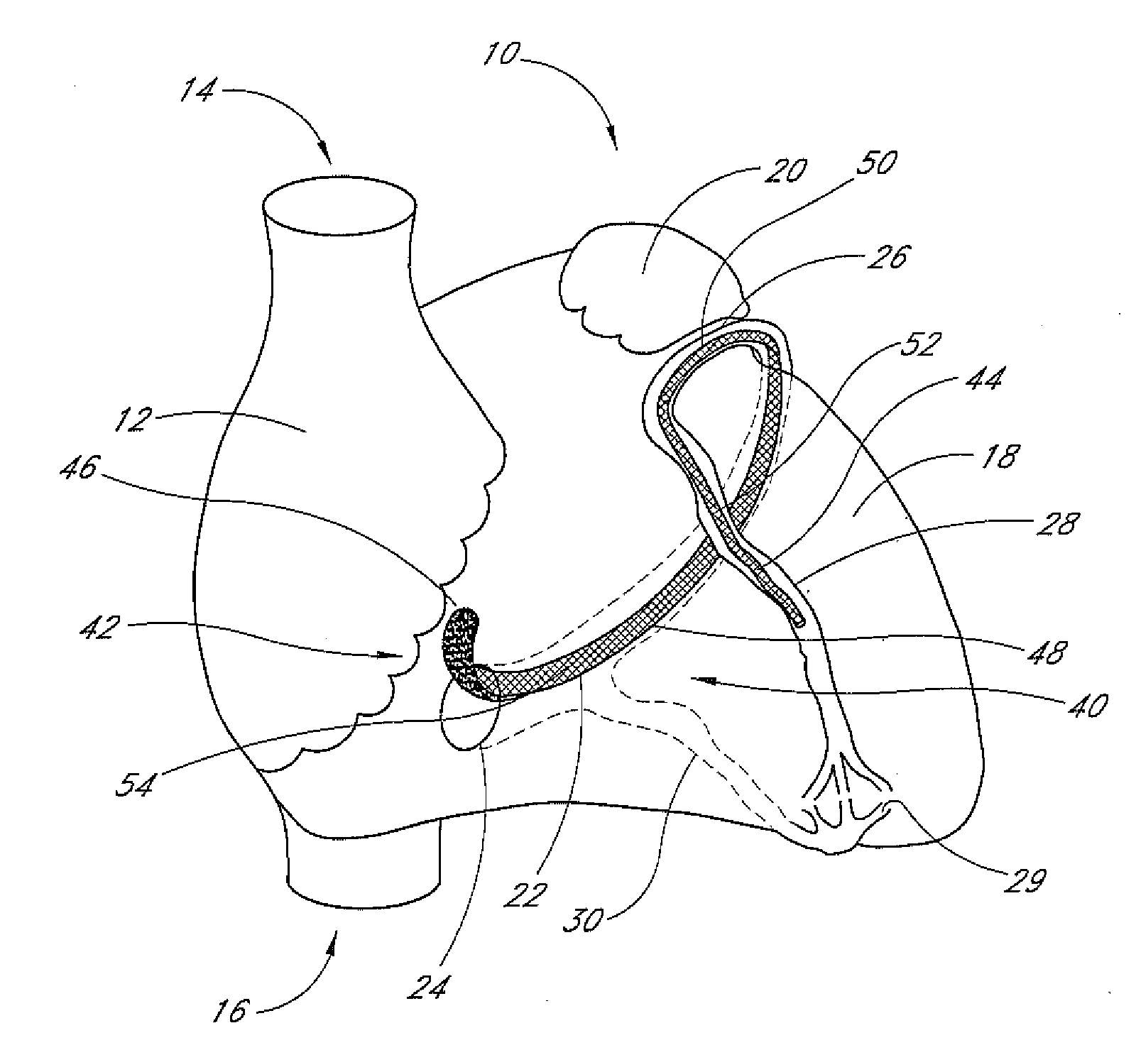
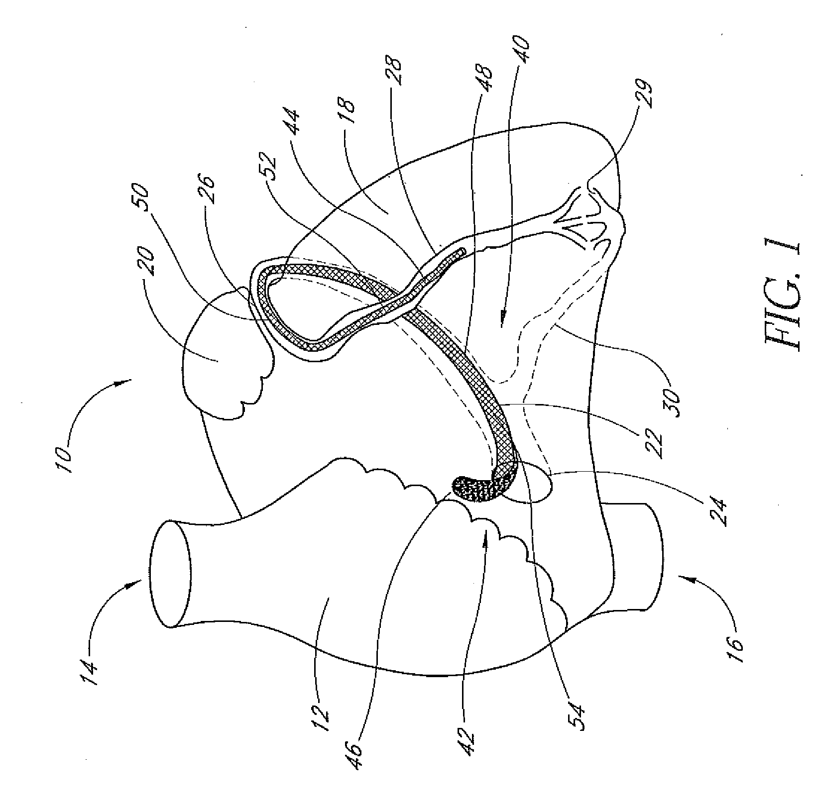
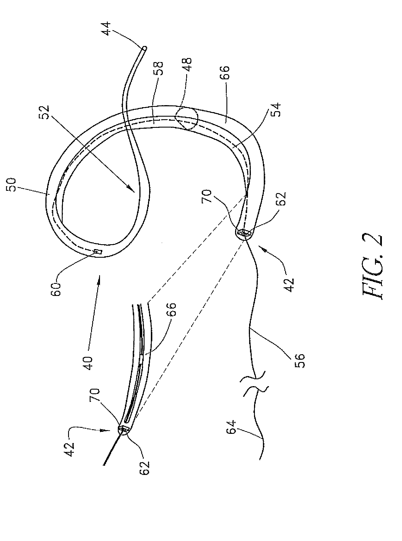
[0028]In accordance with another aspect of the present invention, there is provided an implant for extravascular remodeling, for positioning within a vascular structure to influence tissue outside of the vessel. The implant comprises an elongate flexible support, having a proximal end and a distal end. Each of the proximal and distal ends are dimensioned to reside completely within the vascular system. A forming element is attached to the support, such that movement of the forming element relative to the support changes the shape of the support. The support is thus moveable between an implantation configuration for transluminal implantation and a remodeling configuration for exerting a force against a vessel wall. In one application, the support defines an arc when in the remodeling configuration.

Problems solved by technology

The resulting increase in pulmonary venous pressure and reduction in cardiac output cause congestive heart failure.
This in turn, causes volume overload that exacerbates the myopathy, leading to a vicious cycle of progressive enlargement and worsening mitral regurgitation.
Although mitral valve repair and replacement can successfully treat many patients with mitral valvular insufficiency, techniques currently in use are attended by significant morbidity and mortality.
However, the morbidity, risks and expense of surgical annuloplasty are very high in patients with cardiomyopathy and congestive heart failure.
These techniques may provide some benefits over open chest procedures, but they are still attended by significant morbidity and mortality risks.

Method used


Image

  • Percutaneous mitral annulplasty with cardiac rhythm management
  • Percutaneous mitral annulplasty with cardiac rhythm management
  • Percutaneous mitral annulplasty with cardiac rhythm management

Examples


second embodiment

[0078]the device is comparable to that described above except that it does not contain an axially moveable forming element. Instead, a core of springy memory material such as nitinol or other NiTi alloy is pre-formed to have the required configuration. When the device is pushed out of the delivery catheter into the coronary venous system, the spring force within the core applies the requisite force to remodel the annulus. This embodiment does not require a tensioning element or a tool to disconnect it from the delivery system. However, the magnitude of force applied to the annulus cannot be adjusted.

third embodiment

[0079]A third embodiment is deployed as a loop through the coronary venous system, to form a left ventricular girdle 100. See FIGS. 5-6. The ventricular girdle 100 comprises an elongate flexible body 102 having a proximal end 104 and a distal end 106. A first control line 108 extends proximally from the proximal end 104, and a second control line 110 extends distally from distal end 106. The first and second control lines 108 and 110 may be different portions of the same wire, which extends continuously throughout the length of the body 102. The wire may be a single strand or multi strand component, a length of hypodermic needle tubing, a spring coil, or other structure known in the medical guidewire arts. Preferably, the first and second control lines have a diameter within the range of from about 0.009″ to about 0.018″, although larger diameters may also be used particularly for the first control line 108.

[0080]The distal control line 110 is advanced through an introducer sheath i...


PUM


Abstract

A minimally invasive method of performing mitral annuloplasty is disclosed. An implantable device is positioned within the coronary sinus and tightened around the mitral annulus. Mitral valve regurgitation is monitored before, during, and / or after the tightening step. An on-going drug therapy may be determined, taking into account post-implantation hemodynamic function.

Description

[0001]This is a continuation of U.S. patent application Ser. No. 10 / 806,906, filed Mar. 23, 2004, which is a continuation of U.S. patent application Ser. No. 10 / 715,221, filed Oct. 17, 2003, which is a continuation of U.S. patent application Ser. No. 09 / 968,272, filed on Oct. 1, 2001, now U.S. Pat. No. 6,709,456, which is a continuation-in-part of U.S. patent application Ser. No. 09 / 494,233, filed on Jan. 31, 2000, now U.S. Pat. No. 6,402,781.BACKGROUND OF INVENTION[0002]1. Field of the Invention[0003]The present invention relates to intravascular prostheses and methods of percutaneous mitral annuloplasty while monitoring hemodynamic functions such as mitral valve regurgitation.[0004]2. Description of Related Art[0005]Dilated cardiomyopathy occurs as a consequence of many different disease processes that impair myocardial function, such as coronary artery disease and hypertension. The left ventricle enlarges and the ejection fraction is reduced. The resulting increase in pulmonary v...

Claims


Application Information

Patent Timeline
IPC IPC(8): A61F2/24A61B17/00A61F2/00A61F2/02
CPCA61F2/2451A61N2001/0585A61F2/2466
Inventor LANGBERG, JONATHAN J.LESH, MICHAEL D.
Owner EDWARDS LIFESCIENCES AG
Learn More