
Monopile foundation for offshore wind turbine

a technology of offshore wind turbines and monopile, which is applied in the direction of wind energy generation, motors, artificial islands, etc., can solve the problems of very limited considerations regarding fatigue-induced stress, and achieve the effects of reducing the time of offshore installation, facilitating construction, and eliminating the need for divers

Active Publication Date: 2011-01-13
VESTAS WIND SYST AS
View PDF40 Cites 32 Cited by
  • Summary
  • Abstract
  • Description
  • Claims
  • Application Information

AI Technical Summary

Benefits of technology

[0012]It may be seen as an object of the invention to establish a substructure for a wind turbine tower, where the dimensions and / or the choice of material may be optimised without compromising the mechanical integrity of the substructure. It may also be seen as an object of the invention to provide a method for installing a substructure, where time and effort in installing the substructure is reduced.
[0013]Thus, it may be seen as an overall object of the invention to provide a substructure and a method for installing a substructure which individually or in combination reduces the costs of establishing a substructure for a wind turbine.
[0014]The above-mentioned objects may be obtained by a method comprising the steps of mounting fittings to the secondary structure, said mounting of fittings to the secondary structure preferably being established by welding or bolting, most preferred above sea water level if the substructure is to be mounted at sea, and not mounting fittings to the pile being part of the primary structure, at least decreasing the number of fittings and / or decreasing the damage to the mechanical integrity and thus to the strength and durability of the primary structure when mounting of fittings to the primary structure by means of fixation means involves mechanical or thermally induced material bonding of the pile.

Problems solved by technology

Considerations regarding fatigue-induced stress are very limited.

Method used


Image

  • Monopile foundation for offshore wind turbine
  • Monopile foundation for offshore wind turbine
  • Monopile foundation for offshore wind turbine

Examples


first embodiment

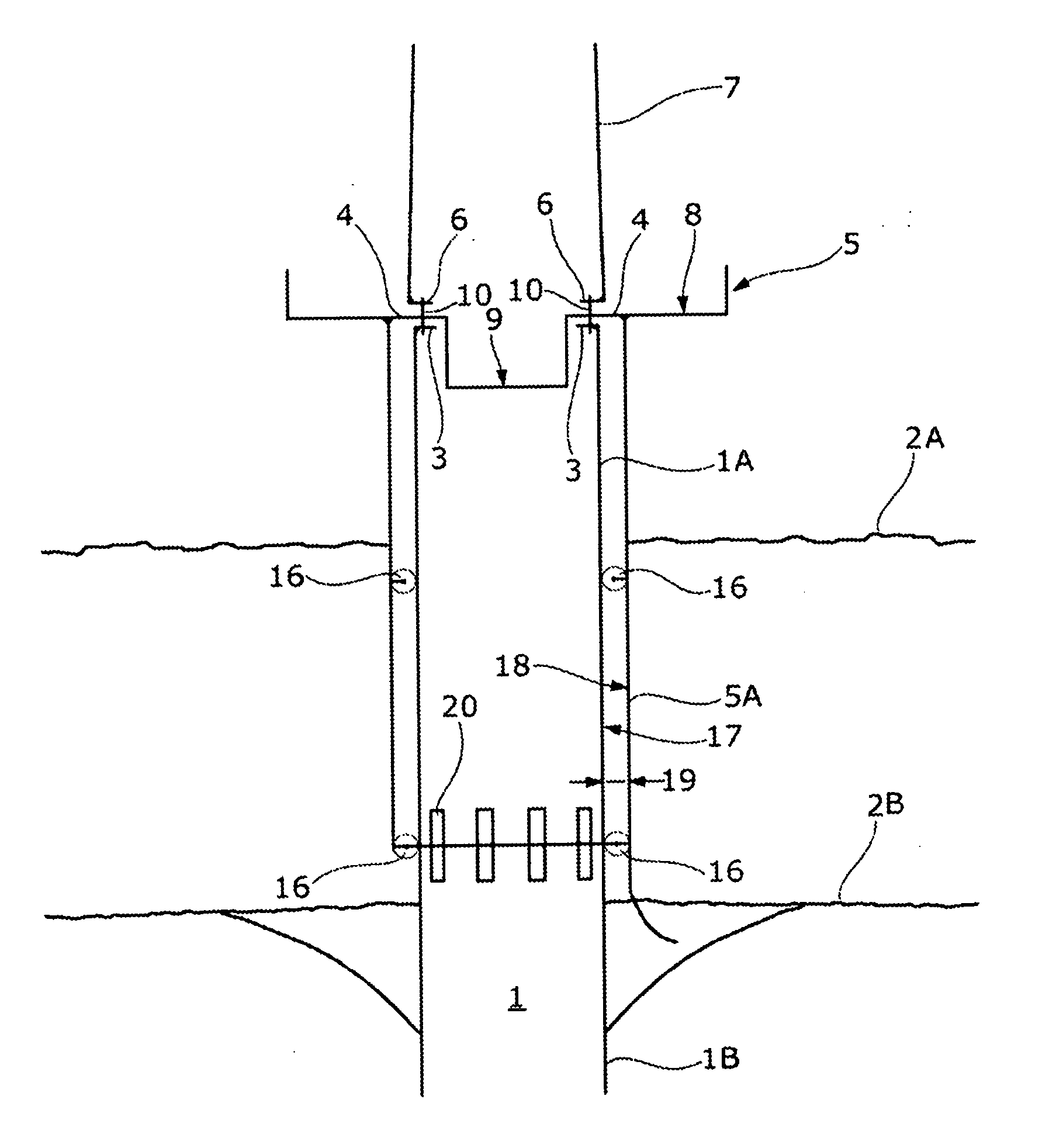
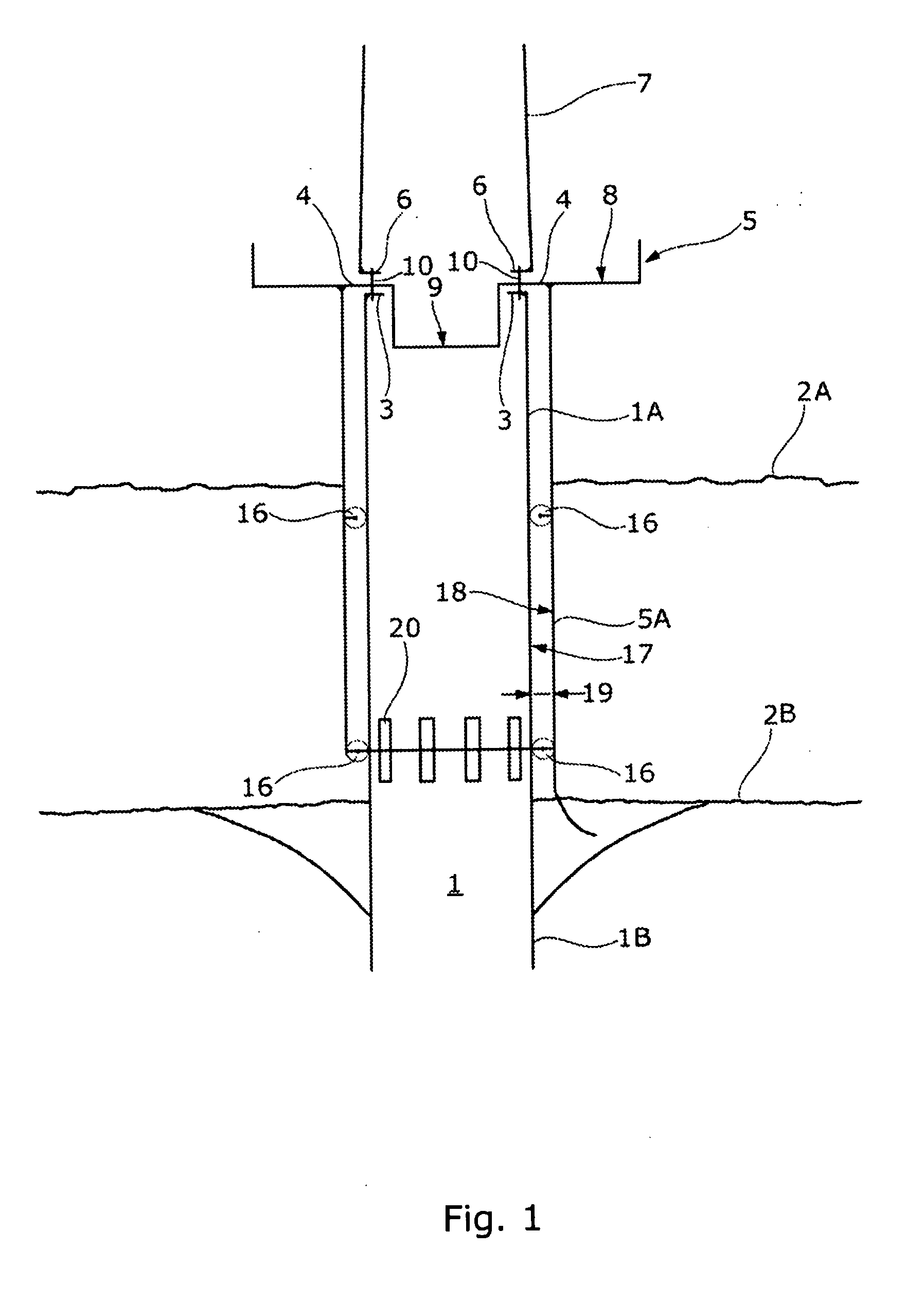
[0049]FIG. 1 is a sketch showing a possible first embodiment of a substructure for a wind turbine. The substructure comprises a pile 1 known as a mono-pile. A bottom section 1B of the mono-pile is partly embedded in the ground 2B, possibly a sea-bed. A top section 1A of the mono-pile is extending above ground and above a possible sea level 2A and is intended for supporting the whole wind turbine and any equipment necessary for mounting and subsequently servicing the wind turbine.

[0050]In the embodiments shown in the figure, the pile 1 is shown to be a mono-pile. Alternatively, more than one pile may be used for establishing the substructure, e.g. three or more piles forming a tee-pee-like substructure. Furthermore, in the embodiments shown in the figures, the pile is shown to be a hollow tubular pile made of steel. Alternatively, the pile may be a solid pile, e.g. made of concrete. Even in the alternative, the pile may be a hollow tubular pile made from another material than steel, ...

second embodiment

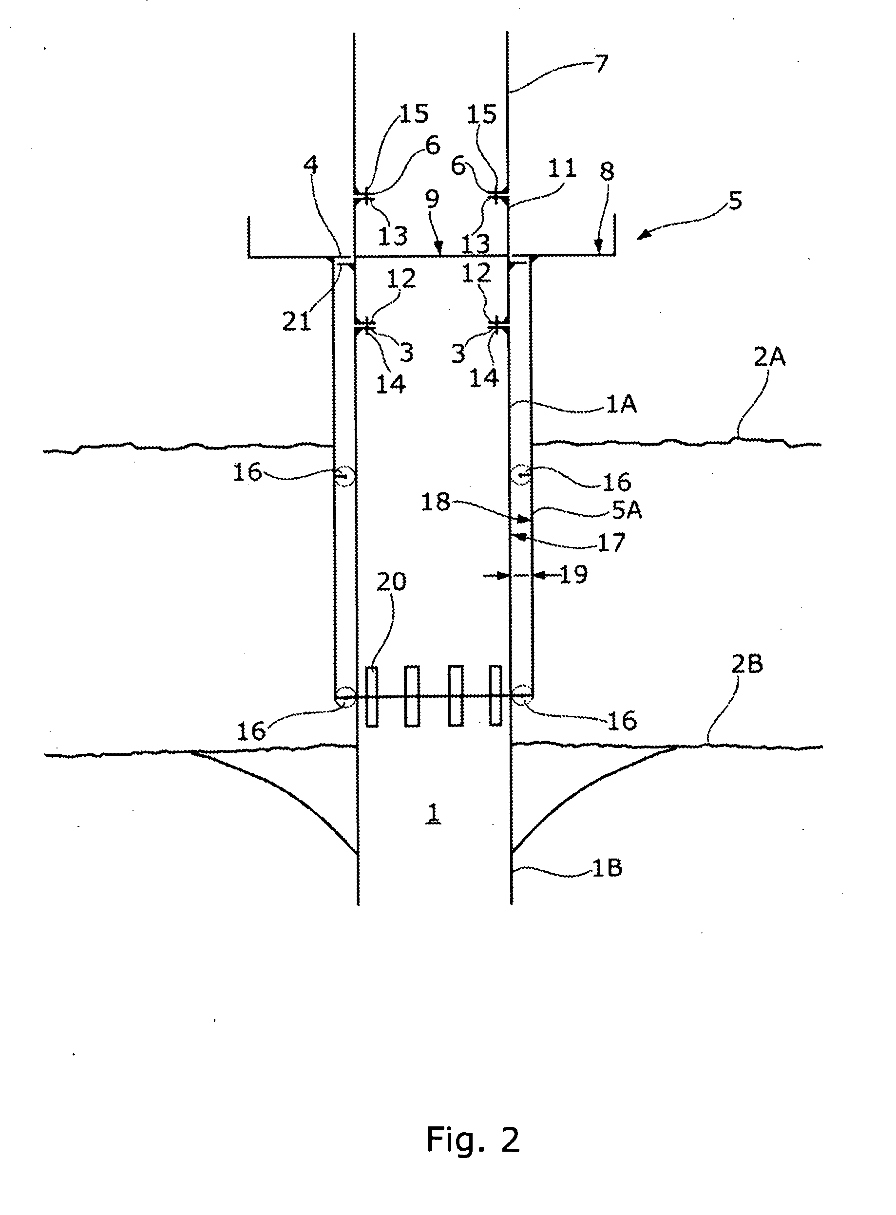
[0061]FIG. 2 is a sketch showing a possible second embodiment of a substructure for a wind turbine. Similar to the substructure shown in FIG. 1, the substructure comprises a mono-pile 1. A bottom section 1B of the mono-pile is partly embedded in the ground 2B, possibly a sea-bed. A top section 1A of the mono-pile is extending above ground 2B and above a possible sea level 2A and is intended for supporting the whole wind turbine and any equipment necessary for mounting and subsequently servicing the wind turbine.

[0062]The mono-pile 1 constitutes a primary structure of the substructure. As mentioned, a primary structure of a substructure for a wind turbine is the structure performing load-bearing of the wind turbine itself including the wind turbine tower. A substructure incorporating a mono-pile is preferably intended for offshore installation, where access to the ground is difficult due to the ground being sub-merged below sea level 2A. The mono-pile is intended for being driven or ...


PUM


Abstract

The invention relates to methods for installing a wind turbine. A method may comprise the steps of establishing a substructure, said substructure comprising at least one pipe (1) extending upwards and said at least one pipe (1) being part of a primary structure of the substructure, establishing a support of a secondary structure (5) on the at least one pile (1), mounting of fittings to the secondary structure (5), said mounting of the fittings to the secondary structure (5) preferably being established by welding or bolting, and not mounting fittings to at least one of the at least one pile (1) being part of the primary structure. A method may alternatively comprise the steps of mounting a wind turbine tower to the at least one pile (1) being part of the primary structure, and the secondary structure (5) constituting an intermediate structure (5, 11) between the at least one pile (1) and the wind turbine tower (7). Even in the alternative, a method may comprise the steps of mounting of the secondary structure (5) to at least one intermediate tubular section (11) being part of the primary structure and mounting the wind turbine tower (7) to the at least one intermediate tubular section (11).

Description

FIELD OF THE INVENTION[0001]The invention relates to a pile substructure being part of a primary structure of a wind turbine foundation, and preferably with welded flange connections, and installed in soft soils by driving with an impact hammer or by vibrating with a vibrator. Due to high installation loads during pile driving or vibration, it is not possible to pre-install attachments to the foundation like boat-landings, access ladders, platforms, J / I-tubes, cranes, navigation aids, cathodic protection system etc., all being elements of a secondary structure of a wind turbine plant.BACKGROUND OF THE INVENTION[0002]Substructures comprising one or more piles, either constituted by tubular sections or constituted by solid sections or even constituted by a combination of tubular sections and solid sections, also known as piled foundation, are known, mostly for establishing a foundation for wind turbines at sea, i.e. offshore. Such substructure consists of a primary structure and a sec...

Claims


Application Information

Patent Timeline
Patent Type & Authority Applications(United States)
IPC IPC(8): F03D11/04E04H12/00E04B1/21
CPCE02B2017/0091F03D1/001F03D11/045Y02E10/728F05B2240/913F05B2240/95Y02E10/727F05B2240/912F03D13/25Y02E10/72E04C3/30E04H12/34E04H12/342F03D13/22
Inventor FISCHER, TORSTENSOE-JENSEN, ANDERS
Owner VESTAS WIND SYST AS
Learn More