Charging device for a shaft furnace

a charging device and furnace technology, applied in the direction of furnaces, charge manipulation, lighting and heating apparatus, etc., can solve the problems of difficult to achieve the difficult to achieve the desired charge profile of concentric circular zones, and hampered formation of coke chimneys, etc., to reduce the effect of abrasive wear of the spreader, maximizing the spreader, and reducing the area

Inactive Publication Date: 2011-01-06
PAUL WURTH SA
View PDF2 Cites 7 Cited by
  • Summary
  • Abstract
  • Description
  • Claims
  • Application Information

AI Technical Summary

Benefits of technology

[0004]The invention proposes a charging device for a shaft furnace that allows, by simple means, centring the trajectory of the charge on the central axis of the furnace.
[0007]The spreader according to the invention makes it possible to divide a flow of material discharged from the hopper and to disperse it, in the form of at least two separate flows, on to opposite sides of the inclined surfaces of the connecting box, that is to say to both sides of the feed channel. When the flows thus previously separated by the spreader come together again, the collision between them is sufficient to reduce or eliminate their horizontal components of velocity, thus creating a flow which is essentially centred, that is to say, essentially coaxial with the central axis of the furnace. Considering such a spreader, it will be appreciated that it is mechanically simple and hence reliable, that it can easily be arranged inside the connecting box and that its installation requires only few modifications to known charging devices.
[0009]In the case of a pivotable plate, the spreader plate advantageously has a geometry enabling it to at least partially cover the feed channel when in operating position. A pivotable plate can be greater in area than a fixed plate. The fact that it can at least partially cover the feed channel when in operating position makes it possible to optimize the spreading of material across the whole channel.
[0010]In an advantageous embodiment, the spreader also comprises a retaining edge by means of which an accumulation of material can be retained on the spreader. Such an accumulation can, in particular, reduce the effects of abrasive wear of the spreader. For efficient division and diversion of the flow of material, the spreader preferably comprises two opposite sides arranged contiguous with the walls of the connecting box.
[0011]In an advantageous embodiment, the feed channel comprises a first upper tubular section and a second lower tubular section, the horizontal cross-section of the first and / or the second tubular section tapering along the direction of material flow. This enables further improvement of the degree of centring of the flow of material at the outlet of the feed channel.

Problems solved by technology

Consequently, the flow leaving the feed channel becomes eccentric.
Thus it is not easy to achieve a desired charge profile of concentric circular zones, and the profile obtained often tends to be rather elliptical.
Furthermore, the formation of a coke chimney, if this is desired, is also hampered.

Method used


Image

  • Charging device for a shaft furnace
  • Charging device for a shaft furnace
  • Charging device for a shaft furnace

Examples


Embodiment Construction

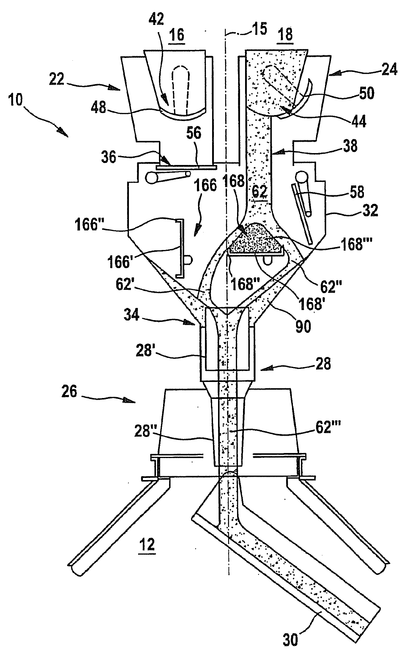
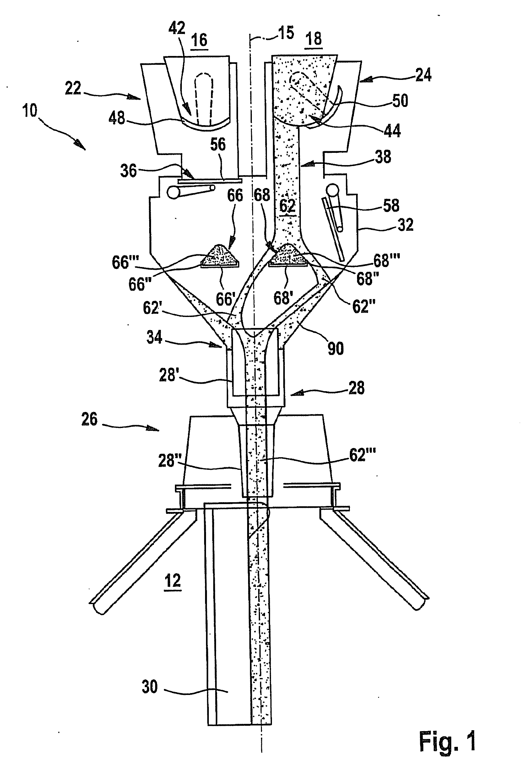
[0018]A charging device, generally identified by reference number 10, is shown as an example in FIGS. 1 and 3. This charging device 10 equips a blast furnace throat 12, which is not shown in its entirety in the drawings. Reference 15 identifies the central axis of this blast furnace.

[0019]The charging device 10 comprises, in known manner, a first hopper 16, a second hopper 18 and a third hopper 20, which act as airlock reservoirs for the material to be charged. Only the lower parts 22, 24 of the first and second hoppers 16, 18 are shown in the drawings. Although the third hopper 20 and its lower part 25 are present, they are not visible in the cross-sections. In FIGS. 1 and 3, it can be seen that the hoppers 16, 18 are arranged side by side, off-centre with respect to the central axis 15 of the blast furnace. The same applies to the third hopper 20. In fact, the three hoppers 16, 18, 20 are arranged symmetrically with respect to the central axis 15.

[0020]The reference number 26 gene...


PUM

PropertyMeasurementUnit
trajectoryaaaaaaaaaa
mass flow ratesaaaaaaaaaa
pressureaaaaaaaaaa

Abstract

A charging device for a shaft furnace, which includes at least one charging hopper having a discharge orifice arranged in a position off-centre with respect to the central axis of the shaft furnace, and a material distribution device arranged below this hopper. The material distribution device includes a feed channel coaxial with the central axis of the furnace and a rotatable, pivotable chute, which is arranged below the feed channel for distributing a charge in the shaft furnace. The charging device also includes a connecting box in the shape of a funnel, arranged between the material distribution device and the charging hopper. The connecting box possesses a lower central outlet communicating with the charging hopper and at least one upper inlet which is arranged off-centre with respect to the central axis of the furnace and communicates with the discharge orifice of the hopper. According to the invention, the charging device includes at least one spreader situated upstream of the distribution device, on the trajectory of the material discharged from the discharge orifice. The spreader enables a flow of material to be dispersed to both sides of the feed channel.

Description

TECHNICAL FIELD OF THE INVENTION[0001]This invention concerns a device for charging a shaft furnace, especially a blast furnace, comprising at least one and in general several charging hoppers which normally act as airlock reservoirs and are connected by a connecting box to a material distribution device with a rotatable, pivotable chute for distributing the charge inside the shaft furnace.BRIEF DISCUSSION OF RELATED ART[0002]There is a considerable number of charging devices of this type that equip blast furnaces around the world. For a blast furnace, charging normally takes place as follows: when a first hopper is being charged under atmospheric pressure, a second hopper, which is then under blast furnace pressure, discharges its load through the connecting box into a central feed channel of the material distribution device. Fed by this central channel, the rotatable, pivotable chute distributes the charge over the charging surface of the furnace. When the second hopper is empty, ...

Claims


Application Information

Patent Timeline
Patent Type & Authority Applications(United States)
IPC IPC(8): F27B1/20C21B7/20F23K3/00
CPCC21B7/20F27B1/20F27D2003/105F27D3/10F27D3/0033
Inventor LONARDI, EMILECIMENTI, GIOVANNI
Owner PAUL WURTH SA
Why Eureka
Try Eureka